Jvc PCXC 70 BK Service Manual

This is the 104 pages manual for Jvc PCXC 70 BK Service Manual.
Read or download the pdf for free. If you want to contribute, please upload pdfs to audioservicemanuals.wetransfer.com.

Page: 1 / 104
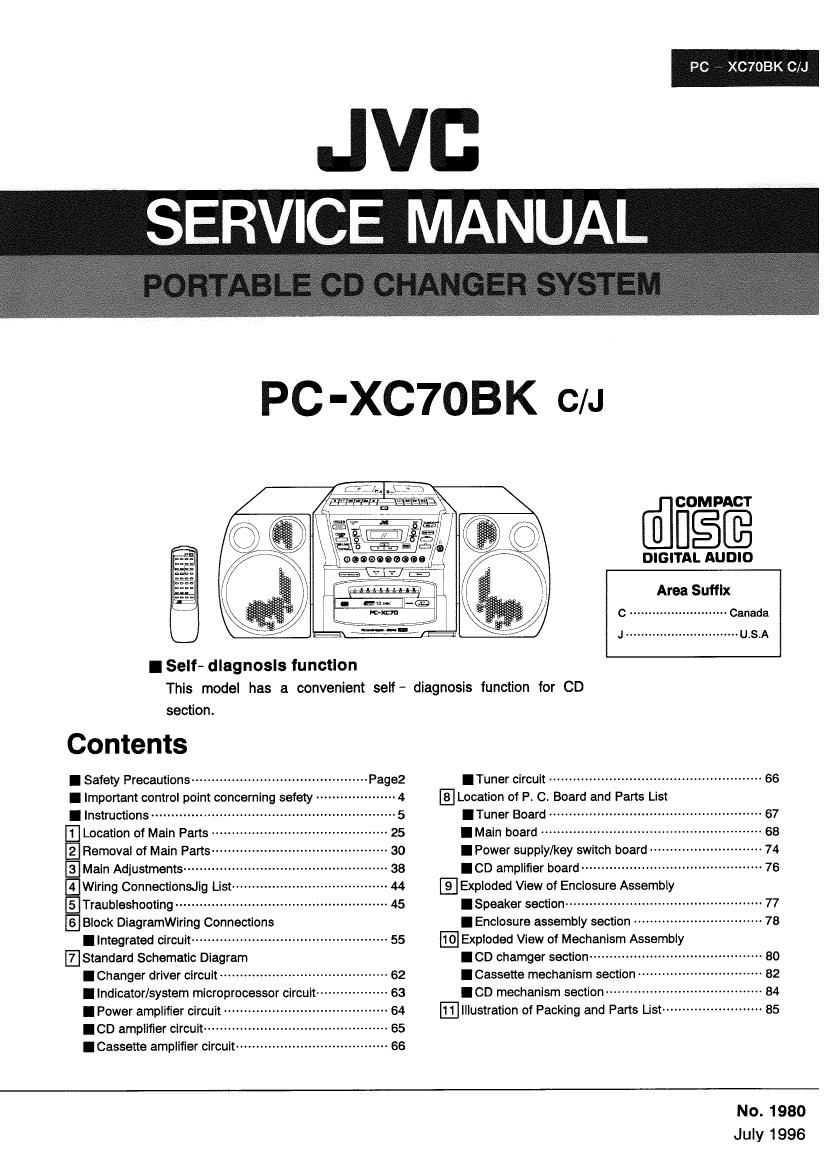
Jvc PCXC 70 BK Service Manual

Extracted text from Jvc PCXC 70 BK Service Manual (Ocr-read)


Page 1

PC XC7OBK C/J

JVC
SERVCE MANUAL

PC-XC7OBK C/J

@figfi

I Selt- diagnosis function

This model has a convenient seIf- diagnosis function for CD


section.
Contents
I Safety Precautions -------------------------------------------- Pagez
I Important control point concerning safety -- 4
I Instructions ------------------------------------- 5
LTJ Location 01 Main Parts - - 25
El Removal of Main Parts- - so
5] Main Adjustments ----- -- 38
Elwrrlng ConnectionsJIg List-~ -- 44
ETraubleshootlng - 45
EIBlock DIagramWiring Connections
I Integrated circuit ------------------------------------------------- 55
'Standard Schematic Diagram
I Changer driver circuit .......................................... 62
I Indicator/system microprocessor circuit ------------------ 63
I Power amplifier circuit ----------------------------------------- 64
I CD amplifier circuit .............................................. 65
ICassette amplifier circuit -------------------------------------- 66

DIGITAL AUDIO
Area Suffix
c .......................... Canada
J .............................. UIS.A
ITuner circuit ..................................................... 66
Location of P. C. Board and Parts List

ITuner Board -

I Main board ------

I Power supply/key switch board

I CD amplifier board -----------------
@Exploded View of Enclosure Assembly

I Speaker section ................................................. 77

I Enclosure assembly section -------------------------------- 78
Exploded View of Mechanism Assembly

.00 chamger section ------------

ICassette mechanism section

.00 mechanism section --------------
Illustration of Packing and Parts List

No. 1980
July 1996

Page 2

PC - XC7OBK C/J l

I Safety Precautions

1. The design this product contains special hardware and many circuits and components specially for safety purposes. For continued
protection, no changes should be made to the original design unless authorized in writing by the manufacturer. Replacement parts
must be identical to those used in the original circuits. Service should be performed by qualified personnel only.

2. Alterations of the design or circuitry of the product should not be made. Any design alterations of the product should not be made.
Any design alterations or additions will void the manufactures warranty and will further relieve the manufacture of responsibility
for personal injury or property damage resulting therefrom.

3. Many electrical and mechanical parts in the product have special safety A related characteristics These characteristics are often
not evident from visual inspection nor can the protection afforded by them necessarily be obtained by using replacement
components rated for higher voltage. wattage. etc. Replacement parts which have these special safety characteristics are
identified in the parts list of service manual, Electrical components having such features are identified by shadinglm) and ( A)
on the schematic diagram and parts list in the service manual. The use of a substitute replacement which does not have the same
safety characteristics as the recommended replacement part shown in the parts list of service manual may create shock. fire. or
other hazards.

4. The leads in the products are routed and dressed with ties. clamps . tubings. barriers and the like to be separated from live parts.
high temperature parts. mpving parts and or sharp edges for the prevention of electric shock and fire hazard. When service is
required. the original lead routing and dress should be observed. and it should be confirmed that they have been returned to
normal, after reassembling.

5. Leakage current check (Electrical shock hazard testing)

After re - assembling the product, always perform an isolation check on the exposed metal parts of the product (antenna

terminals, knobs. metal cabinet. screw heads. headphone jack, control shafts. etc.) to be sure the product is safe to operate

without danger of electrical shock. Do not use a line isolation

AC V0 LTMETER
transformer during this check. m (Having 1000 ohms/volt,

- Plug the AC line cord directly into the AC outlet. using aLeakage or more senmrvlty.)

,
current tester. measure the leakage current from each exposed :-J
. F P

metal part of the cabinet. particulary any exposed metal part 015 AC TY E

____
having a return path to the chassis. to a known good earth ground. Place this probe

J on each exposed

Any leakage current must not exposeed 0.5mA AC(r.rn.s.) 1500 n 10 W metal part.

- Alternate check method
Plug the AC line cord directly into the AC outlet. Use an AC Good th ground
voltmeter having 1.000 ohms per volt or more sensitivity in the following manner. Connect a 1,500 ohms 10W resistor paralleled
by a 0.15 [I F AC type capacitor between an exposed metal part and a known good earth ground. Measure the AC voltage
across the resistor with the AC voltmeter. Move the resistor connection to each exposed metal part. particularly any exposed
metal part having a return path to the chassis. and measure the AC voltage across the resistor. Now. reverse the plug in the AC
outlet and repeat each measurement, Any voltage measured must not exceed 0.75V AClr.m,s.),This corresponds to 0,5mA

AC(r.m.s.).

The lightning llash with arrowhead symbol. within an
CAUTION equilateral triangle. is intended to alert the user to the
presence 0! uninsulaled dangerous voltage" within the
DO NOT OPEN product's enclosure that may be of sufficient magnitude
to constitute a risk of electric shoot to persons.

CAUTION: TO REDUCE THE RISK OF ELECTRIC SHOCK. I
DO NOT REMOVE COVER (on BACK). .7 The exclamation point within an equilateral triangle is
NO USER-SERVICEABLE pARTs lNSlDE. intended to alert the user to the presence of important
REFER SERVICING TOOUAUFIED SERVlCE PERSONNEL. 933? and maintenance (servicing) insmlilims i"
the literature accompanying the appliance.

A CAUTION

Burrs formed during molding may be left over on some parts of the chassis. Therefore, pay attention to
such burrs in the case of preformlng repair of this system.

2 (No. 1980)

Page 13

PC - XC7OBK C/J

9.6.5: u

as... .. §a5&.§§ .
8.....aaeu. 29.98.. .
do m... :33 232. .

E: 3...

3%.... .55

is... 33
.3: . iiéaiss.
a... is... a 2.... .
2...... .5. .. 3...... 2:... .

can: .35.:

fig

55.58

8... .3 a... .. .539... a. 2.8.5 was. .s is: .
95.... .3 .3328 . «.8 .3. 8 .mu 5.395 .
.. 5.3.9.. as. .333. a... B o... 3.5.5.. .

:3! Eu Gary-:1 u: c: an
8.5.3.5 ..=u..u§.=.......ss.. a
65...... o. J... v a. 5...... 22.1 a: .

.35.}. w... 59.2.... 3

1...... w... .8 3.»... 3 .38 5....

E. a... 26% a. 3...... m. m 3.35..

2.53.... 3. 2. 2a..» a. «.33...

m. 23.3 .33.. .3 3...... on .5? -
3:3... .5... 81.3.3. ..

Emu .s 33.... m... 2......»

3. 2.... $3.3m... an .3... .3...

In 2...... $53.35.. 3...... 8 .w

a... amazowmins 3.33.3 2...»... ..
5&3

:3 Eu... 2.2.... a. 55 on 333%

.333... my 32... 5... .5... 3.3. .
35.2.5 .0

3.3.. a. .2... my. .2 .

.25....

as... 8.. w. .3 2.... E .2... 5... a... .

25.2.8...

$.33...» 3...... u. as... .8 o...
8.9....

3.. 8:232»... 2 .3 8.5.2.... .«

«ESE
33...... a. SE... 2...... «an 52......
«.33.... noautszasii 3:56 .

2:33 mien Ea Esafi 2i. ...m.3§.
u 23...... a... .8399: SEEK $8.3
a. gauge...» 3.5% m8 .293 m. 2.....8.

50.53:: 323 o 38.. av

8.8
3 was. :8 _w .32. 232.9%.
33.9... mm 8%.. no m3 0......

9.3 E. S. n 5.9. 3.3.... 3333
.028 a 99.... no .3 .823 on 3.5. n
no 0.. Haas... ..

S... a .885... a... 2. 53:28
:2 cu mw-:O.Co>o.a $553953. m a ..0m
.8 2...... N... m. a 8 3. 3.8.. oz .
a...
a s. s. a... 253.8 3 $2.9...
.395 a. 8 8 S as... 2. $.38 .
25.52.82.

no no. a .8 oz .

832m 90 3... m. 2.5. oz .
no no 3.02.3.5... 2:3 is: d

886.... 8.9.. a. .8 no 8......
335...... no .

2.9.9. B. N 3.3.... 5
£55.32. 95. .39.... m. .28 $3...
333... o 33.... 85.5 no 8. 2.5

.53 sing»:
.23: ES: 2...... .5... 83.5. .

.38 a... 2 .2...»
w... E... 23. 9...... .5 u no 2.
530 as.» =8 . 55m 12:...
a... E»... a... do a 9.6.8. 22... -
30 95.50 ..


.25 .o 56.5....
5... . 2. .2... a .5. 35.2352
.3... 59...... as... 280 $3.29. 8 .
.35 3 ... v.93 .. .3 a.
a... x ....... 2.52.8. 8.25:3... .
2.5.6 5

30 9.3 .9. on a
on.»
E... .5 ..o 3...... 2.... .o .3... .2 an. u
8......
398». a .02... o... 5.5. .2. on. .
.3 2.65.. .a 8.3. .

Es... .5... m... a... .8 3:
:5 .33.. .

Fig.2
g... 9.659. 23 9.5 .5... 2. came...
.2. 30 3...... Eu Samson . 6 85m

ww30_¢mS:zo_DD<
mm Dam-D wwn 29515553.:-

no ma 290531.212

nno OZZDZ

t

.. .82.... 2...... 8 $.33 2...... w. $3.. a. a $2....
at... as... .o 5...... mm
63 2.... SE a... £3 .. 2... .39... 83% .235

2.9.... 88 a. 3.8.3.8. u. on.

$3»... 2.3... £3 on). 3. E...
3.36 3. Eu... 2.3 m. 2.5.. .35.... .

mmmmma @552 mu umxfi mwn E0532 m:
3...»... 3.2.... m m. 2.5... mamas... .
.mwaumfi mg... m. E223 tm
>(Jlm_n goaoh

«Enema.
3...... m. 5...... 0......»
m... .5... 2...... $325.35....»
3...... .mm 55.22.... 2.. .3... m. .
2...... m... 3.3%..
an .. 3...... . .m 05.. 2......
a. .3 231.... .8... 3 52...... .39.
fans... 8 S .39.... my 5.28....
m... .m 3.3. m2 3.... m... m 3.9.3.
u§§.§m..¢..m...mc§§ . 3.
(9.5.2.2... a. 8.... s. .55....
2me 35.8 .3 .333... on
5...... .2... E... 03.3 28.. m.
.3 Ngiam 25.. 95.5 ...e..m..2.e_..m..
an 3...... E .......u.....m...e...m 8......
.53... 5...... a... 2... m 22....
.3 .8 55...... $28 a. 9.26


«a 5.3.3... €5.55... 3......
5:23.363 u 26... on 2.23»

$3.693. an .5... RE m

3.38 9......
«as... an 93......
.35.... an:

/ .3 \3 I. .
math. ... 1....-.

flab.

89.93.. .23 2mm .8 no 5.89%.
a 8&5 35.....3 a. 5.3.... 5.03.2.5 .

13 an a... 2......
.23 S a... 22....
an... s 5...... .5...

2...... 8 9.... 3.8
9.... is... S

Wméfiht

8.5.3.. 23 5.8 2% . .5... 9. 8
8. 853 25...... a. 2mm... .83.... 3 .
.00 03:. 3 am: Qm on «so

>(._Lw_fl Egan

32.3328

35.. N. 2%.... 8...... . m. 3

nu 9% sum. 33 0...»...8..9S.=.
83a .55 59.... mo 39.. w o
96.... u
.m m. «552.8»... 3.02%.
can; a... 3.853
a... .3383 89 8.93.28 .3
33 5 . 9....

3 a... .m 5 $6..

mm. 3.3.635. «a 89.. .m m...»
Ems. M 828.83.. 3 can... a.
2. 59...? m. «5.5.... .053 3.2.
.m 9.93... 8.». 8.5.6 5.3.32...
3 8.... .m 2...... 9.5.:
3.... .3... m. <0 3 2. .89.... .m
S «u 8 {8.8 .m 2.2.8 3 8.5.6
.«o 5.32.... :2. 8 8.3...
55.8.... .89.. 3.. =39.


.832. 8.5.. m... s... 8.... 9..
Eu m... .33 5.5.... m... .3... 3...... 2: .

5.. 5....
. I.
3....

name. .35.. a... 5.; 8.5.. 8.. 2

So .9... 9...... o. a... as... in... 2. .

3.... no a... 3.. 5....
SE... >336

22.5823 2%..
m. .2 3:9.» 9. 3 .3... 3.8.3
3 2.5.. a. .3... 9.: 2: .
.3 35. m an
_. 3.2.3 2.... 9.. 9... 5.5.. 02.3 a...
as. .88. u .3... a ,x $3.35...
39.2. no... 2.. a... 5.3.83
5 2......» .69.... .536 a .3
2286.. SEE... 2.3.2..» 3
.22.... m. .28 a... 2. 0...... .85..
02mg 9.. 32a .6. 5...... 3.2.2:"
«.2. 8.62. 125...... 2...»... us...
2.. 8.52.. a. 98 .39. 3 2.. :2...
.3... .. 33R.
9. =2... :5. :2... .3... 9......


$39.29....» .3 .8 m. 23 323...... ...
3.3... 2.58 a. a 3.585 3. 2......
m an a. .2... ..........n: .2 a. :3... .3
3.5.2.3.

.. .6 E Nimnugwas
m. 8 :8 m. :9. .3 3. 2.8 .2. .m 3.
>_._
39...... 9.9.. m3 3.... .2... .3 $53
25...... u. 3 .3. SEE 2.3 .a him
.530

.289.

3 3.5.53 2.92.... a. Eggs... 2.
2.5.2.... m. u.» s... 55.8 2.3 .3. .m

ca
8.... .6

.8. 393... w. 5.9.... 2...... ..... on...
.53.. m. .6 .. .32... .3 3. .2...
F

61%.... 2.3%.

m. 0.. $38. E 5%... 2.3 .8 .23..
nus-E

3.5.5.235. as...» .23... in. 2...
.23 on .3... .i 5.523

.33.... m. 3 8... a is...
a: Ema fibre :a D mevo>flfi me. an DUEDm
3 8.3 m. 2. 2m 0.3 8.3. 2. .88. m3

is:

o)... 5 E. .u a E

00 09:3 Emu c9923 man (a 06:00 U

2..

3.5.32.2.

S... .8 6...... . $5.528 3...;

.8 8a.... 93 5.93.. 93 S 9.2.8.8

.530

.89 . 5.2.2. 8.3... 8.5.20...

9w. 8.9.. 2... 5.38 «.3 S 0.33 u

on

8.. Se
8 new... a .8. 2.8 .2 833 o

:3 8.3... m... .. 2.8 a... S 22558

;.um

8.3.. m3...

9....me 8.....3 5.0.8.. 2% 5 92.3.8

.5...

3.5.33.5. 2...: 8 .28.» so. 2....

8...: .u .3... .8 5.8.3

jlilj

w

.3. E28 $.29 :8 n. 8.... n. .339.

z» 333 326. m. m... m... 325 .
Sn 8 .38. 2.05.285.

33 $33. .53. a. .3 5.33 n

m... «29...... a. 3.. w. 5...... 38
3.... .33 m...» 52.3 a» m. 3.9.. 3..
.3. on 2.2.. a. 2......

.. 15E: AI mum AI Emu T23...

.55...
2.9....w m. 8 5...... 3.8m 3 89..
.w 9.38 6.... .a 9.9.... a... 3. «Eu .
09.8 mu .8... a
5.28%. $3 0238 .22 .m 9.93.. .

863.98. 09.3 E. 3.
8.3... mm o... .m. .3 a 83.. 3.3
.3 $33. 3...; ma 88:. 8..

3...... on .3... 2. =23


,9. .8... 5.... 953 2:3...
.9. 8 .2: 2.2%.... .o 39...... u... a...
52.... .53 05.3.; 2... $3... 9.... 2:

3.2.

9.3...
5. o... .0 9...... o... .2 8.68 m... 2 .3
m):

.22. 62329. g... 33..

9.655 a... a... 9...... 5...... «

a... .32 a... .538
as m... a. 3
do.

.585... 9%.... Em.

.3... 8m... 5 .8
.52. in... a 5... 23... .o. 5.52. m

a... a. 9:3... 5.... 5:5. a. 2 .3
35.6522... s... .33 258 a... .2...
5.....8 32.. 9:3

Ming-E aw $9.55 as: 9.28

as 832.. m. 5.5.. 2.38 a... or... 53 a
.03.:

958 2. 3.3 o. .2... 938 a... 3...... .

3...... as... 3.... .. 2...
2.. 8......» a. 3.3.3 3 .8 was... 2:3
=2... £5... 253

(No. 1980) 13

Page 29

PC - XC7OBK ON

I Rear cabinet inside view
POwer supply board assembly

Power trans former

Tuner board assembly

Fig.1 -9

(No. 1980) 29

Page 33

I CD changer section

9 Removing the CD Mechanism Holder
1. Remove the four screws ® retaining the CD mechanism
hoider.

2. After turning over the changer unit, remove the two
screws ® retaining the shield plate and one screw ®
retaining the CD amp.

3. Remove the shield plate of the pickup unit, and raise the
CD amp. P.C. board assembly. Next, disconnect the
two wires connecting the P.C. board and CD
mechanism. as well as the pickup card wire (CN601)
and motor wire (CN602).

OCIamper Unit
1. Remove the two screws ® retaining the clamper unit
from both sides of the mechanism.

2. After opening the bottom side of the clamper bracket a
little toward outside, remove the bracket.

3. Remove the'sensor P.C. board as necessary from the
ciamper bracket (For this purpose, remove the one
screw retaining the P.C. board).

0 CD Tray (Disc Base)

* Under the conditions wherein the laser pickup has been
raised, lower the pickup while turning the gear G4 (L) of
the CD mechanism unit fully in clockwise direction. Then,
it will become ready to pull out the tray.

1. Alter pulling out the CD play by about 50 mm, remove
the one screw (9 retaining the stopper bracket provided
on the right side of the tray.

2. Pull out the tray fully to the movable position,and turn
over the changer unit.

Chassis

Stopper bracket
\ Approx. 50 mm

Pull out the CD tray

CD tray so that this cut section
is positioned roughly
to the chassis.

Fig. 2-12

Open the lower
5 part to outside
and remove the _.

PC - xczoBK C/J

Mechanlsm holder
(Chassis holder)

t/

V i
i
i

1 U
' {pg As

CD changer mechanism Assy
Fig. 2-9

Pickup card wire

CD amp.
board assy

Motor wire
Fig. 2-10

Open the lower
part to outside
and remove the _.

(No. 1980) 33

Page 35

3. In case the CD mechanism unit cannot be removed
smoothly, turn the gear G4 (L) in the counterclock- wise
direction. Then, the CD mechanism unit will be removed
smoothly.

< Assembly>

1. insert the CD mechanism holder boss on the left side of
the CD mechanism unit Into the groove of the gear G4
(L).

2. Set the stopper on the right side of the CD mechanism
holder onto the chassis and fix the chassis with the
related screws.

< Plckup Assy>

1. Remove the two right and left screws retaining the
pickup shaft stopper.

2. After moving the pickup to outside while turning the gear,
pull out the shaft and remove the pickup while turning
the pickup at the corner in clockwise direction.

6 Gear Chassis Unit

1. From the upper front surface. remove the one screw (9
retaining the chassis unit.

2. From the left side surface, remove the two screws ®
retaining the chassis unit.

3. For protecting the switch, remove the one screw (11)
retaining the switch PC board from the back side.

4. From the upper surface, remove the two screws ®
retaining the right side of the gear chassls.

PC - XC70BK C/J

Pull out the CD mechanism.

Stopper

' _ Press this part and
L remove the stopper.

The CD mechanism


A _ ll-l; _lI--
Gear G4 (L) CD mechanism unit

While turning the gear G4 éB Wt be firmed up
counterclockwise, set the and WW"-
mechanism chassis nearly to
garallel (Then, the pickup will

e raised), and remove the Fig. 24 7

CD mechanism.

Turn table

Chassis

Gear G4 (L)

Insert the shaft into the gear G4 (L). Stopper

Fig. 2-18

While turning the pickup clockwise
by making use of the comer,

Pickup unit remove the pickup.

ole

Turning direction In case the pickup
unit is moved to outside.

Fig. 2-19

This washer should be inserted

between the chassis bracket and

gear shaft. Switch P.C. board
bracket.

(No. 1980) 35

Page 40

PC - XC70BK ON

I Cassette and amplifier section

difference between the REC/PB level of the
input signal and PB level of the VTT724 test
tape is within 0 i- 3dB.

Item Gonbltlcns Adjustment 3. Confirmation Methods Stand. values Adjust
Head azimuth - Test tape * Adjust the head azimuth screw only when the Within 2dB of Head
adjustmentf : VTT703(10KHZ) head is replaced. the peak lebel azimuth
(A, B mechanism) - Output terminal (D Playback test tape Vll703 (1 okHz). Minimum adjusting
for measurement ®Adjust the head azmiuth so that the phase phase screw
: Headphone difference is minimum (Within 2dB of the peak difference
- Input terminal for level of play output.) After adjustment apply
measurement the screw locking adheslve to the head
: CN301 azimuth screw more than a halfl arund the
screw head.
Tape speed - Tast tape (DWhen playing test tape V1171 2 (3kHz). . Tapre speed VR761
adjustment and : VTI71 2 (3kHz) ®Adjust VR761 so that the frequency counter : 2990Hz~
wow & Flutter - Output terminal reading is 2990Hz-3010Hz. 301on
checklng for measurement ©Wow & Flutter should be less than 0.4% (JIS
(A, B mechanism) : Headphone UNWTD). Wow & Flutter
: Less than
0.4% (JIS
UNWTD)
Play back output - Tast tape (DWhen Playback the test tape \fl'T724 (1 kHz), - 24dB i adB
level checking : VTl724 (1IHZ) the output level at headphone is - 24dB
(A, B mechanism) - Output termlnel i sdB at 1kHz.
for measurement ® Deviation L and Ft : less than 3dB.
: Headphone
Playback - Tast tape When playback the test tape VTT739, response saHz and
frequency : VTT739 should be - 5:13 i 4dB at 63Hz and 1kHz. +5dB 1kHz
response checking - Output terminal i 4dB at 10kHz and 1kHz with respect to 1kHz. : - 5:13 i 4dB
(A, B mechanism) for measurement 10kHz and
: Headphone 1 kHz
+5dB i 4dB
Adjusting the bias Test tape: ©Connect a frequency counter (with a 1M (2 101 .1kHz L7341
oscillation AC - 513 resistor inserted in seriesl)to the L7341 i 1kHz
frequency Measured output secondary side erase pin.
pin: (2 Load the test tape (AC - 513)in the deck and
Oscillation coll set to Record - Pause mode.
secondary slde ©Adjust the L7341 so that the frequency
(erase) counter level reads 101 .1kHz 1 1le in
Record mode.
Record/playback - Reference ®Record and playback the 1kHz reference
frequency frequency frequency and 10kHz signal and check at
response : 1 kHz, 10kHz treminal 0N301 .
adjustment (Ref. - 20dB) @Adjust the VRA41 so that record and +5dBf§dB VR741
(A mechanism) - Test tape: playback frequency response with 1kHz and
A024 10kHz at CN301 is i odB : 1dB.
- Output terminal @ Comfirm that the frequency counter reading is 101 .1 kHz L7341
for measurement 101.0kHz i 0.15kHz. If the reading is out of i 0.15kHz
: CN301 this range, adjust L7341.
Record/playback - Test tape: While recording/playing back sn input signal of 0 i 3dB
sensitlvlty check VTT724, A6224 the reference leve (REC level), confirm that

40 (No. 1980

Page 47

Error- identified
times

1 1

Flow charts

Does it remain on
Inner/outer area?

I peraie without a
disc

Does laser turn
on?

Does obieci lens
move upldown?

Defective points

1

Fesd "IMO!
Motor connacuon
Gear

Rust swiich

Laser daiacm'e

Focus aduakor delaclivu

Error- identified
times

1

Flow charts

1
9

PC - XC7OBK C/J

Defective points

1


Does spindle
motor spin?

mndle rumor
(or connecilon

Y
Can TOC be
read?

Tracking servo
Tracking aclualor
Pickup

Y

(No. 1980) 47

Page 99

PC - XC7OBK C/J

O Cassete mechanism assembly parts list

(3}

BLOCK

N0.I_l:-I|

A REI, PARTS NO. PARTS NAMIC REMARKS Q'IY SUFFIX CIAR
A 1921123187T MOTOR ASS'Y NO.58;6B 1
1 192114316T BASE ASSY 2
2 19211LO9T SWITCH ACTUATOR 2
3 19211438T PUSH B.ACTUATOR 2
4 19211422T BUTTON LEVER REC BUTTON 1
5 19211484T BUTTON LEVER PLAY BUTTON 2
6 19211424T BUTTON LEVER REW BUTTON 2
7 19211425T BUTTON LEVER FF BUTTON 2
8 19211426T BUTTON LEVER STOP BUTTON 1
9 19211461T BUTTON LEVER PAUSE BUTTON 1
10 19211413T P CONT. SPRING 1
11 19211455T PAUSE LEVER (E) 1
12 19211412T SPRING PAUSE LEVER 1
13 19211411T PAUSE STOPPER 1
14 19211414T TORSION SPRING BUTTON LEVER 2
15 1921015012T CHASSIS ASS'Y 2
16 19211416T TORSION SPRING E.ACTUATER 2
17 19211417T TORSION SPRING P.S.LEVER 2
18 19211464T E KICK LEVER 1
19 182101159T E.KICK LEVER 1
20 19211420T STOPPER 2
21 19211421T TORSION SPRING REC BUTTON 1
22 19211415T TORSION SPRING BUTTON LEVER(C) 1
23 MSW-1541T LEAF SWITCH MSW-1541T 2
24 18210150T PLAY BUTTON LEV 2
25 19210311T HEAD PANEL 1
26 19210314T HEAD PANEL 1
27 19210304AT HEAD BASE 1
28 19210306T HEAD BASE 1
29 19210309T PANEL P SPRING 2
30 19211418AT SPRING M CONTROL 2
31 19211434T P.ROLLER ARM 1
32 99992041T SPECIAL SCREW M 2 X 3 1
33 18210308T SPRING 1
34 18210307T AZIMUTH SPRING 2
35 192104309T P.ROLL. ARM ASY 2
36 640101161T LEAF SWITCH MSW-17820MVDO 2
38 19212604TT SENSING LEVER 2
39 192107308T RF CLUTCH ASS'Y 2
i9 18210711T RF.BELT 2
4.1 19211466T BUTTON LEVER 1
1.2 19211433T TORSION SPRING 1
43 1921093042T FLYWHEEL ASS'Y PB MECHA.(B) 1
44 19210930311' FLYWHEEL ASS'Y REC/PB MECHA.(A 1
45 192126OST TORSION SPRING GEAR PLATE 2
46 192126SOZZT GEAR PLATE ASSY 2
47 19212602T CAM GEAR 2
49 18211070T F.FORWARD GEAR 2
50 18211099T BACK T.SPRING 2
51 192105304T S. REEL ASSY SUPPLY 2
52 1921OS303T T. REEL ASS'Y TAKE-UP 2
53 19210506T SENSOR 2
SS 19211211T MOTOR BRACKET 1
56 18211266T MOTOR RUBBER 3