Jvc MXD 501 T Service Manual

This is the 110 pages manual for Jvc MXD 501 T Service Manual.
Read or download the pdf for free. If you want to contribute, please upload pdfs to audioservicemanuals.wetransfer.com.

Page: 1 / 110
Jvc MXD 501 T Service Manual

Extracted text from Jvc MXD 501 T Service Manual (Ocr-read)


Page 1

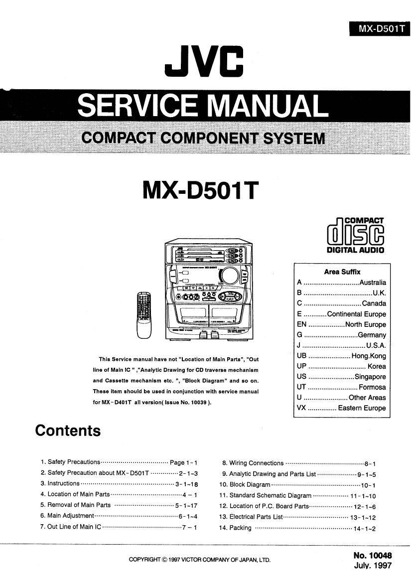
MX-D501T

MX-D501T
[@ng

DIGITAL AUDIO
Area Suffix
Australia
....... U.K.
C .............................. Canada
E ............ Continental Europe
EN . ..... North Europe
G ............ Germany
J ................................. USA.
This Service manual have not Location of Maln Pans", Out UB """"""""""" Hong'Kong
line of Maln lc " ,"Analytlc Drawlng for CD traverse mechanism UP ' """"" > Korea
_ US . ....... Singapore
and Cassette mechanism etc; ". "Block Dlagram" and so on.
. . . , . UT .......................... Formosa
These Item should be used In conjunction wrth servrce manual
f Mx D40 " . (I N 10039) U .......... Other Areas
0? 8 VBISIOII ssue D. .
VX ., Eastern Europe

Contents


1. Safety Precautions ---------------------------------- Page 1- 1 8. Wiring Connections -------

2. Safety Precaution about MX- DSO1T -------------- 2- 1 -3 9. Analytic Drawing and Parts List ------------ --9- 1 ~5
3. Instructions ----------------------------------------------- 3- 1~18 10. Block Diagram --------------------------------------------- 10-1
4. Location of Main Parts ----- ---~4 - 1 11, Standard Schematic Diagram ------------------ 11-140
5. Removal of Maln Parts 5- 1 ~17 12. Locatlon of RC. Board Parts --------------------- 12-1~6
6. Main Adjustment ---------- ~~6-1~4 13. Electrical Parts List~~ ' 13-1~12
7. Out Line Of Main |C ........................................ 7 -1 14. Packing ............................... 14.1-2

No. 10048

COPYRIGHT © 1997 VICTOR COMPANY OF JAPAN, LTD.
JUN. 1997

Page 2

MX-DSO1 T

1.Safety Precautions

.The design this product contains special hardware and many circuits and components specialty for safety purposes. For continued

protection. no changes should be made to the original design unless authorized in writing by the manufacturer. Replacement parts must
be identical to those used in the original circuits. Service should be performed by qualified personnel only.

Alterations of the design or circuitry of the product should not be made. Any design alterations of the product should not be made. Any
design alterations or additions will void the manufactures warranty and will further relieve the manufacture of responsibility for personal
injury or property damage resulting therefrom.

. Many electrical and mechanical parts in the product have special safety related characteristics. These characteristics are often not

evident from visual inspection nor can the protection afforded by them necessarily be obtained by using replacement components rated
for higher voltage. wattage. etc. Replacement parts which have these special safety characteristics are identified in the parts list of
service manual. Electrical components having such features are identified by ( A )on the schematic diagram and parts list in the
service manual. The use of a substitute replacement which does not have the same safety characteristics as the recommended

replacement part shown in the parts list of service manual may create shook. fire. or other hazards.

. The leads in the products are routed and dressed with ties. clamps , tubings. barriers and the like to be separated from live parts. high

temperature parts. mpving parts and or sharp edges for the prevention of electric shock and fire hazard. When service is required. the
original lead routing and dress should be observed. and it should be confirmed that they have been returned to normal, after

reassembling.

. Leakage current check (Electrical shock hazard'testing)

After re~ assembling the product. always perform an isolation check on the exposed metal parts of the product (antenna terminals,
knobs. metal cabinet. screw heads. headphone jack. control shatts. etc.) to be sure the product is safe to operate without danger of
electrical shock. Do not use a line isolation transformer during this check.

- Plug the AC line cord directly into the AC outlet. using a"Leakage current tester". measure the leakage current from each exposed
metal part of the cabinet. particulary any exposed metal part having a return path to the chassis. to a known good earth ground. Any
leakage current must not exposeed 0.5mA AC(r,rn.s.)

- Alternate check method

. . , AC VOLTMETEFi
l .
Plug the AC Ine cord directly into the AC outlet Use an AC voltmeter E23 (HM!!! 1000 ohms/volt,
having 1.000 ohms per volt or more sensitivity in the following manner. or more unsirlvlry.)
Connect a 1,500 ohms 10W resistor paralleled by a 0.15 .11 F AC type 3
capacitor between an exposed metal part and a known good earth 0.15 MF AC TYPE
ground, Measure the AC voltage across the resistor with the AC '
Puc- this probe
voltmeter. Move the resistor connection to each exposed metal part, . on net: expend
1500 n 10 W metal part.

particularly any exposed metal part having a return path to the chassis,
and measure the AC voltage across the resistor. Now. reverse the plug C1004 earth 9'00

in the AC outlet and repeat each measurement. Any voltage measured

Warning ( Except to C/J/U version )

i. This equipment has been designed and manufactured to meet international safety standards.

2. it is the legal responsibility of the repairer to ensure that these safety standards are maintaintaind.
3, Repairs must be made in accordance with the relevant safety standards.

4. it is essential that safety critical components are replaced by approved parts.

5. If mains voltage selector is provided. check setting for local voltage.

A CAUTION

Burrs formed during molding may be left over on some parts of the chassis. Therefore. pay attention to
such burrs in the case of preformlng repair of this system.

Page 5

I IMPORTANT (For C/J Version)
: Fuse Replacement Marking Check

Fuse Caution : Graphic Symbol Mark -

mm

[

< 3

F999

F997

-ower Su - ol Board
F998

MX- D501 T C/J

Full Fusereplacernenl Marking

Graphic symbol mark (This symbol means fast blow
type fuse.)

should be read as follows:

FUSE CAUTION

MX - D501 T C/J

MX-D501 T

[ Marquage Pour Le Remplacement Complet De Fusible I

Le symbols graphique (Ce symbols signifie fusible de

type 5 fusion rapids.)

A

doit étre interprété comme suit:

PRECAU'HONS SUR LES FUSIBLES

F999 : FOR CONTINUED PROTECTION
AGAINST RISK OF FIRE, REPLACE ONLY WITH
SAME TYPE 1.0-A, 250-V FUSE.

F998 : FOR CONTINUED PROTECTION
F997 AGAINST RISK OF FIRE, REPLACE ONLY WITH
SAME TYPE 1.25 - A, 250' V FUSE.

F999: POUR UNE PROTECTION CONTINUE
CONTRE DES RISQUES DINCENDIE,
REMPLACER SEULEMENT PAR UN FUSIBLE
DU MEME TYPE 1.0'A, 250'V.

F998: POUR UNE PROTECTION CONTINUE

F997CONTFIE DES RISOUES DINCENDIEY

REMPLACER SEULEMENT PAR UN FUSIBLE
DU MEME TYPE 1.25 'A, 250 V?

2-3

Page 13

MX-D501 T

w-

...2... ._ 58...... .. =53... .
:2... .385 =22. .3: =3 .5. is E. 3.3.. 5.8:... 55: 0... Jan... 3.3. a... E Ea flew 5.5.2..
520.2: u... i... a. 3:5. 3..on u... .6 5...: mac: .2... u... so... auvzo etc: o... 23.9. a...

.85 3.2. E. a. Bu... :5 5.6.9... 5:38.. 25...... a... =. a: 2.3.55.1; .6202: v... a... S
.E.....u 0.2.3. 0... ..e 5...... mac: 2... v... .3... .32. .5 2.8a. a. v.2. .. $83.5 35.. S... .3 :23

23: 5.3.3.5: E... 0.: 09.5.0 eh

Janna .
5...... 2t .35.: 5511!. a... _ .iuvti. u .2... $39... on =1» 3.9.5.-
930... I: .3399 2...?» B a. .5 Yuan-3.... a. 3.5 0.: 2 20-55
n.
U

die-IE «any... I, 5...»
BEE-E :- 25: a. «:13 .5» £3.30 sell 5. n . p at... «:50: .9,

.m .2 .32.. 9.. 8.0.38 «.5. .5...
a. 5.5. .35.... o... 3:» 5:3 0... 85.8. 1...... 336.2. E. .89... 0... $732.28 332..
.. .9. 2.. .. is. .35.... u... 228.. E. 3. a... .29... u... 5 .52.... is... .82.. 2...

.00.... 5...; 2+ o... 9:3»... .u... 2.3.3.: 2 . u... :9...

5n S E 235:: S35 .3

.55.... 2+ 2... .53»... .3: 2.2.59. 2 . a... an...

"on 3 = 235.... Sun... 5..

.3. a. .5... .5. .32.... 88... o... .2 3.. .35.... a... a»...

.c- o. v 23:5: $3.... .6».

$7503.55... .2250 33...:

o..- .5 on... non-Ea: 0.: 9.10.... an 53......- 5005 0.: Egg-o .6,

£6.13 l 3:. 2.:- Oa :3...- n: 03.235. .9 is 02-33h 0.: oven in .

£63.:- I$E 0.: 357 35.90.... h.- E I «on-on .v

9...»... 55.38.. 2: 9:32.... b. r25... 8... =3... 3»

25....» u... .3»... :8 as. .S..u.=.=..... a 5.. . ._. .523... 2...»; 5:2... .3»... .95. a... v2.5.5
.55: u... 8.... .25. u... 5. 39.8.5... 15... 53 a»... 8.3.252. .5. 5.82.3 =. 3.92
ESE... .82.. u... .8. £53. :2 2 o. .... .2: 25.5. 2.. an e. ..= .8»... =3 :5

9.035% 9.5000...-

.c§u_%... .. .252. 3.8.9. o... ...
.ézva. :38... a... .33.... .. .35.... a... a... .35.... «so... 2.. .3523 2,... 2K .2... .
..I l . .
I. .I..
.o. 5...»...22422. .3 .Scflus... .o. .3...
s... a»... .3 .25... a. ,m 5... 2+ .3... .m. 3...... s. a .3... .n .85..» 5. sass... .
.226 39:3. 2. .o in. .85.... u... c. .33.... Eu... 2.. 5.2.5 B 5...»... 2. 60.8 .«
.... e2... 8...... .58. .8... u... 2.89. :8 E... I... 9. :3... 32.2... u... :2... ..
3-39 «on: :- 05.- 3 .D-Ea IE 0.3 on: 8.! :lo 35>

5.5. .82... .3: o... a. on a. 5:3 .5 m .AA x. 2.58 .n. Y! 0... 0.8.2 .x... 8.... .3...
5.5.5. «5.38... Be. :5 03.3.. I
do
.95.... 23.. .59.... a...» 3.2.5.. o... .=. 19...... 5.35. n 5...? .39... u... .5 9.3.5...
35% muse-50... 0:. .m_x.ouon 3.0. u S. .55.... n5 dz-2:5 .a 238 mvz_23._. n... 22. "Eu .3: I
«O
ASE-5.15.35. 1.53 :6» 0.5 u... we: .5.» :2...
g 62. 2 E959... E0.- PS... 2 .2353. :2...» g... 02.23... .5 238 02-23 u... unpr- I

6111111111.. Ego-on I coo-On 3 can? 09......
.2< Ea 2. :82». SEE... 3.... 2.1.5.5.. u... 58... 3.. 3.... =8...

5:... SSE n... .3... D a ,

o-EIn hail-.30; :85!- n.._..0a_.<.w 3;:

3...... 2.. S 23.3.1.5... 3.8.x $8.3... a... .o .25.»... 2...
5.2. u... .5 E... o. 5...... 252.. a... .3...

553% a :- m..._......_. l

m.

5.5 2.. .u..e...m 2.8... a... o. 3.. 81.5.8 «E5 2.1.5... N... a 23...: E< 82. 3.5.58 2.5

as...» 252". 2.9.1.»... .3 £3. 2.. o. 8...... 2:3 .2... .2.- EE. 5...... =8 =a> I 9.
,... 3.5. 5...: .58. .5... v... 9.15.. :2. E.- ...5 2.. .8 E... 3 5.5.. .232... a... up... a...

9-1.: 93-. 0:0

s
3......
o... .5 23.... L. : 2x. ....... a... S 5...... 238 «.22.... 2.. 9...... 2...... 5...... .53....

u... .532. B .s E... .32.. 2.925 5 .. e... a... a... e... a. i... a 2 .8. 0...... a l
.33... w;

0_.. .5 5...... 5.x 2.... .....= u... E. 5...... a: DEE... u... 9...»... 2...... 5...... «mac.
2.. 9.32.. b. .s .5... .35... .5525 u. ._ .5. 2.1.22... 3. .35.... . u... 6%. a. I
9.5... E. o. 5 .s .. as... u. m .a 3-. 5
.32... .2. a 2.3 .. Esau 2. 3%.... 5.5. I
9.3... .2. c. 2.. 8:53.. 22.2.3: .55... +
.2... 23. 9.13.5 3...: o... .6530 2...; 9.3... "2.. ¢ 8.. a: .2... 2:8 2.» 6.1.53 ,

[11a 05°C..» its... 3.5... !< 0.: 95:0
.3 0...... 8m. .2585. 2...... o.- ifi... 2.. u... E u... 5.... a... .396 .

5...: 2.. a. .55.... 2%.. I

$22» base... Ev...

ES. 5 ....8......§..» x........... c. .85.. 3 :3 2.2.5 ..S.§. $2 a... .2". 5.... a. :2... :3 =8.

5.52 a... s 3.53.. 2.2. a... SS... ~£5 2.... a... 53......
.3... 9. 2.3. .2... $2.. 3...... 2.1.3... 9...... a 52.... 2.. 5.5

59.9. a... 3:6 . .8522. .20 We
3 .3222... 58 9V

189$ 8.123 .2 awn-u: AV \re
a

0
i...§s......a.....s \
g§§$§$§§§ M.

.25.... .8»... 5...... .335... .35... E...


238 52.23
.5 02.2...»

1:... .AA alllv
230D... V!

.05.... 05 magma-i

3-8

Page 34

MX-D501 T

(CD Traverse Mechanism Sections)

I Removing the CD Servo control board
(See Fig. 5- 35).

1. Remove the Metal cover.

2, Remove the CD Traverse mechanism assembly.

3. From bottom side the CD Traverse mechanism
assembly, remove theone screw ® retaining the CD
Servo control board.

4. From the connectors CN601, CN603. CN604 on the CD
Servo control board, disconnect the card wire. from the
connector CN602. disconnect the Spin connector wire.

5. Disengage the two engagements "A" , remove the CD
Servo control board.

I Removing the CD tray assembly
(See Figs. 5- 366-38)

. Remove the front panel assembly.

. Remove the CD Traverse mechanism assembly.

. Remove the CD Servo control board.

, From the T. bracket section "B and clamper base
section "C", remove both of the edges fixing the rod
(See Figs. 5-36 and 5- 37).

5. Remove the screw ® retaining the Disc
stopper(See Fig, 5- 37).

6. Remove the three screws (3) retaining the T. bracket
(See Fig.5-37).

7. Remove the screw @ retaining the clamper
assembly (See Fig. 5* 37).

8. From the left side face of the chassis assembly, remove
the one screw (53 retaining both of the return spring and
lock lever. (See Fig. 5- 38)

9. By removing the pawl at the section "D fixing the return
spring, dismount the return spring (See Fig. 5- 38).

10. Remove the three lock levers (See Fig. 5-38).

#wN-l

T.Bracket DISC stopper

Lod stopper
(C/J version only)

3

/ Fig.5-38

Lock lever

5-10