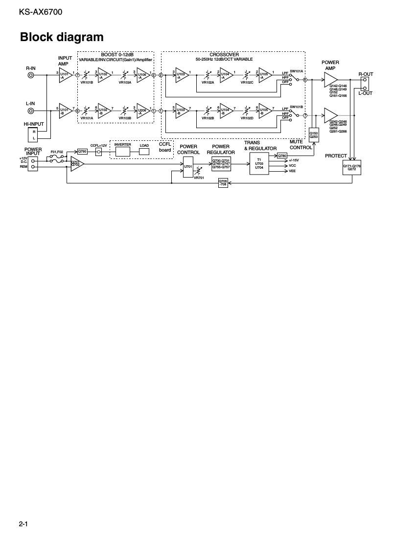
Jvc KSA 6700 Schematic
This is the 6 pages manual for Jvc KSA 6700 Schematic.
Read or download the pdf for free. If you want to contribute, please upload pdfs to audioservicemanuals.wetransfer.com.
Extracted text from Jvc KSA 6700 Schematic (Ocr-read)
Page 1
6 5 4 3 2 1 BCDE FGH I J A 7 KS-AX6700 2-2 Caution If electricity is connected during disassembly, it must be a no load current. If it is load current, be sure to attach a heat sink to the power-amp IC. This will be damaged if the above precautions are not followed, as it does not have a sub heat sink attached to it. Indicates main signal Standard schematic diagrams Main board and sub [1/2] /sub2 board circuit diagram SUB2 PCB SUB1 PCB
Page 2
6 5 4 3 2 1 BCDE FGH I J A 7 KS-AX6700 2-3 Caution If electricity is connected during disassembly, it must be a no load current. If it is load current, be sure to attach a heat sink to the power-amp IC. This will be damaged if the above precautions are not followed, as it does not have a sub heat sink attached to it. Main board [2/2] and CCFL board circuit diagram CCFL PCB Parts are safety assurance parts. When replacing those parts make sure to use the specified one. CCFL - Inverter board