Jvc KDSC 900 R Service Manual

This is the 50 pages manual for Jvc KDSC 900 R Service Manual.
Read or download the pdf for free. If you want to contribute, please upload pdfs to audioservicemanuals.wetransfer.com.

Page: 1 / 50
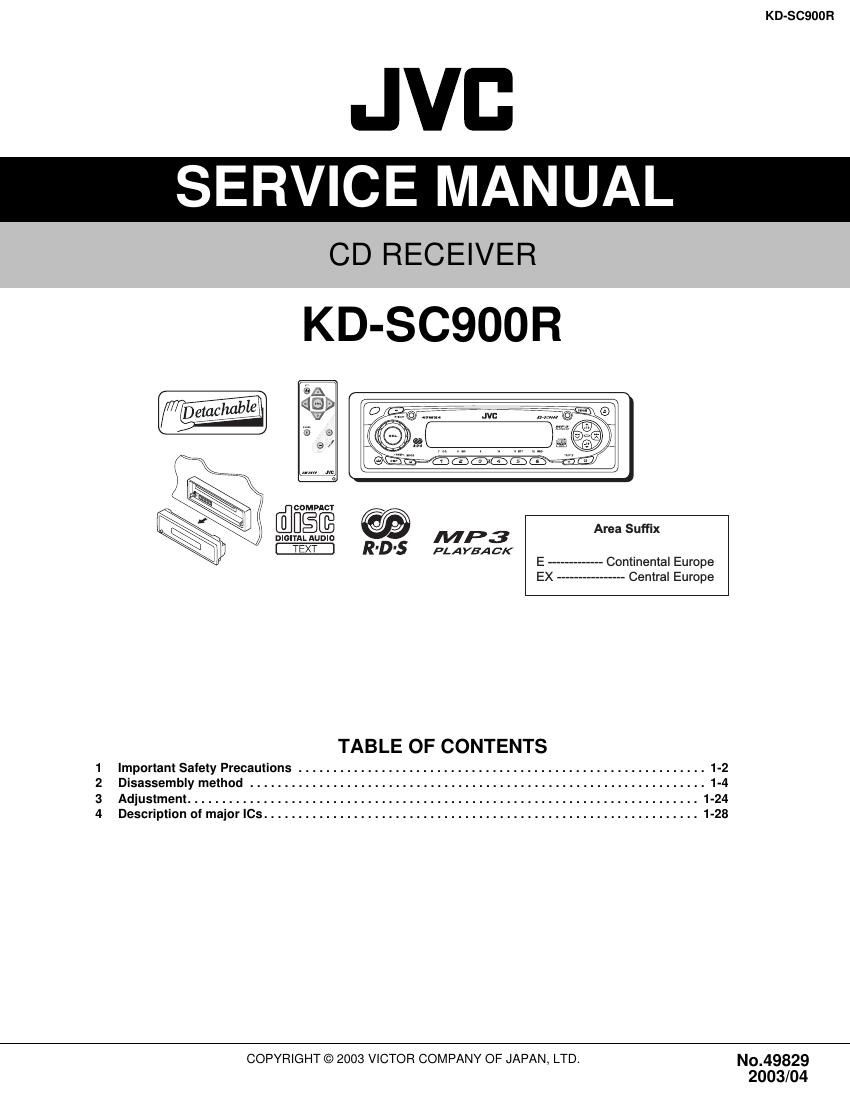
Jvc KDSC 900 R Service Manual

Extracted text from Jvc KDSC 900 R Service Manual (Ocr-read)


Page 1

KD-SC900R 1-2 (No.49829) SECTION 1 Important Safety Precautions 1.1 Safety Precautions ! Burrs formed during molding may be left over on some parts of the chassis. Therefore, pay attention to such burrs in the case of preforming repair of this system. ! Please use enough caution not to see the beam directly or touch it in case of an adjustment or operation check.

Page 2

KD-SC900R (No.49829)1-3 1.2 Preventing static electricity Electrostatic discharge (ESD), which occurs when static electricity stored in the body, fabric, etc. is discharged, can destroy the laser diode in the traverse unit (optical pickup). Take care to prevent this when performing repairs. 1.2.1 Grounding to prevent damage by static electricity Static electricity in the work area can destroy the optical pickup (laser diode) in devices such as DVD players. Be careful to use proper grounding in the area where repairs are being performed. (1) Ground the workbench Ground the workbench by laying conductive material (such as a conductive sheet) or an iron plate over it before placing the traverse unit (optical pickup) on it. (2) Ground yourself Use an anti-static wrist strap to release any static electricity built up in your body. (3) Handling the optical pickup - In order to maintain quality during transport and before installation, both sides of the laser diode on the replacement optical pickup are shorted. After replacement, return the shorted parts to their original condition. (Refer to the text.) - Do not use a tester to check the condition of the laser diode in the optical pickup. The tester's internal power source can easily destroy the laser diode. 1.3 Handling the traverse unit (optical pickup) (1) Do not subject the traverse unit (optical pickup) to strong shocks, as it is a sensitive, complex unit. (2) Cut off the shorted part of the flexible cable using nippers, etc. after replacing the optical pickup. For specific details, refer to the replacement procedure in the text. Remove the anti-static pin when replacing the traverse unit. Be careful not to take too long a time when attaching it to the connector. (3) Handle the flexible cable carefully as it may break when subjected to strong force. (4) I t is not possible to adjust the semi-fixed resistor that adjusts the laser power. Do not turn it. 1.4 Attention when traverse unit is decomposed *Please refer to "Disassembly method" in the text for the CD pickup unit. - Apply solder to the short land before the flexible wire is disconnected from the connector on the CD pickup unit. (If the flexible wire is disconnected without applying solder, the CDpickup may be destroyed by static electricity.) - In the assembly, be sure to remove solder from the short land after connecting the flexible wire. 1M (caption) Anti-static wrist strap Conductive material (conductive sheet) or iron plate PickupShort-circuit point (Soldering) Flexible wire Pickup Short-circuit point

Page 39

KD-SC900R 1-40 (No.49829) 4.14 TA2157FN-X (IC521) : RF amp - Terminal layout - Block diagram 24 ~ 13 1 ~ 12 12 11 10 9 8 7 6 5 4 3 2 1 13 14 15 16 17 18 19 20 21 22 23 24 20k 20k 15k 20k 20k 3k 180k 240k 240k 15pF 15pF 40pF 40pF 10pF60k 60k 22k 22k 94k 94k 14k 50k 20k 20k 20k 40k 50k PEAK 15k 40k 2k 1.75k 1.3V 2k 1k 180k 3k 12k 12k 20k 40k 30k 10pF 50 A BOTTOM PEAK K 1x0.5 x2 x0.5 x2 PIN SEL (APC SW)TEB (TE BAL)RFGC (AGC Gian)TEB (TE BAL) VCTRLPIN VCC APC ON -50% +12dBNormal mode (0dB) HiZ APC ON 0% +6dBNormal mode (0dB) GNDAPC OFF (LDO=H)50% 0dBCD-RW mode (+12dB)

Page 44

KD-SC900R (No.49829)1-45 - Pin functions Pin No Symbol I/O Functions 1 /RESET I Hard reset input H:normal L:reset 2 MiMD I Micon I/F mode select input 3 /MiCS I Micon I/F chip select input 4 /MiLP I Micon I/F latch palus input 5 MiDio I/O Micon I/F data input/output 6 /MiCK I Micon I/F clock input 7 MiACK O Micon I/F acknowledge output 8 VDDT - Power supply for digital (3.3V) 9 SDo O Data output 10 BCKo O Bit output 11 LRCKo O LR clock output 12 SDiO I Data input 0 13 BCKiA I Bit clock input A 14 LRCKiA I LR clock input A 15 SDiL I Data input terminal 1 16 BCKiB I Bit clock input terminal B 17 LRCKiB I LR clock input terminal B 18 VDD - Power supply for digital (2.5V) 19 STANBY I Standby mode control input H:STBY L:normal 20 VSS - GND for digital 21 VSSL - GND for DAC Lch 22 VRAL - Reference voltage for DAC Lch 23 LO O DAC Lch output 24,25 VDAL,VDAR - Power supply for DAC Lch/Power supply for DAC Rch (2.5V) 26 RO O DAC Rch output 27 VRAR - Reference voltage for DAC Rch 28 VSSR - GND for DAC R ch 29 TESTP I Test terminal H:test mode L:normal 30 TXO O SPDIF output 31~34 Po0~Po3 O General purpose output 0 ~ 3 35 VDDT - Power supply for digital (3.3V) 36~38 Po4~Po6 O General purpose output 4 ~ 6 39 REQ O REC terminal 40 VSS - GND for digital 41 IRO I/O External interrupt input 42 VDDM - Internal 1Mbit SRAM power supply (2.5V) 43,44 Fi0,Fi1 I Flug input 0,1 45 VSSM - GND for internal 1Mbit SRAM 46,47 Pi0,Pi1 I General ourpose input 01 48 VSS - GND for digital 49,50 Pi2,Pi3 I General purpose input 23 51 Pi4/CLCL I General purpose input 4/SUBQ I/F clock inputoutput 52 VDD - Power supply for digital (2.5V) 53 Pi5/DATA I General purpose input 5/SUBQ I/F data input 54 TSTiN/SFSY I Test terminal/SUBQ I/F flame sync input 55 Fi2/SBSY I Flug input 2/SUBQ I/F block sync input 56 VSSP - GND for VCO 57 Pdo O PLL phase error detection signal output 58 Vcoi I VCO control voltage input 59 VDDP - Power supply for VCO (2.5V) 60 CKo/CKi I/O External clock input/Clock output terminal 61 VDDX - Power supply for X'tal oscillator (2.5V) 62,63 Xi,Xo I,O Oscillator connection terminal for input/output 64 VSSX - GND for oscillator