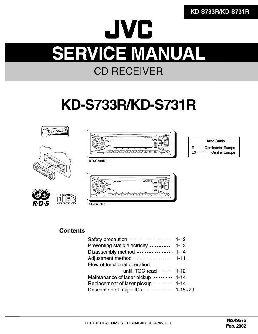
Jvc KDS 733 R Service Manual
This is the 51 pages manual for Jvc KDS 733 R Service Manual.
Read or download the pdf for free. If you want to contribute, please upload pdfs to audioservicemanuals.wetransfer.com.
Extracted text from Jvc KDS 733 R Service Manual (Ocr-read)
Page 1
KD-S733R/KD-S731 R
JVB
SERVICE MANUAL
CD RECEIVER
KD-S733R/KD-S731 R
Area Suffix
E - - - Continental Europe
EX ------- Central Europe
COMFACY
RlDls DIGIQEJEE KD-S731R
Contents
Safety precaution ------------------------- 1- 2
Preventing static electricity -------------- 1- 3
Disassembly method --------------------- 1- 4
Adjustment method ------------------------ 1-11
Flow of functional operation
untill TOC read -------- 1-12
Maintanance of laser pickup ----------- 1-14
Replacement of laser pickup -- - 1-14
Description of major ICs ----------------- 1-15~29
No.49676
COPYRIGHT (2;) 2002 VICTOR COMPANY OF JAPAN, LTD.
Feb. 2002
Page 2
KD-S733R/KD-S731 R
Safety precaution
A CAUTION Burrs formed during molding may be left over on some parts of the chassis. Therefore,
pay attention to such burrs in the case of preforming repair of this system.
A CAUTION Please use enough caution not to see the beam directly or touch it in case of an
adjustment or operation check.
Page 6
KD-S733R/KD-S731 R
l Removing the main board
(See Fig.7 and 8)
- Prior to performing the following procedure, remove
the front panel assembly, the front chassis assembly,
the heat sink and the bottom cover.
1. Remove the screw B, the two screws C and the
three screws D attaching the rear bracket on the
back of the body. Remove the rear panel.
Rear panel
D
. . Fig.7
2. Remove the two screws E attaching the main board
on the bottom of the body. Disconnect connector
CN501 on the main board in the direction of the
Main board
arrow.
CN501 Fig.8
l Removing the CD mechanism section CD mechanism section
(See Fig.9) F F
Top chassis
- Prior to performing the following procedure, remove i.
the front panel assembly, the front chassis assembly,
the heat sink, the bottom cover and the main board.
1. Remove the three screws F attaching the cassette
mechanism section on the back of the top chassis.
Page 7
l Removing the control switch board
(See Fig.10 to 12)
- Prior to performing the following procedure, remove
the front panel assembly.
1. Remove the four screws G attaching the rear cover
on the back of the front panel assembly.
2. Unjoint the ten joints c with the front panel and the G
rear cover.
3. Remove the control switch board on the back of the
front panel.
Front panel
KD-S733R/KD-S731 R
Rear cover G
Fig.10
Joints c
Rear cover
Joints c
Fig.11
Control switch board
Fig.12
Page 15
Description of major le
I TEA6320T-X (IC161) : E.vo|ume
KD-S733R/KD-S731 R
1.Pin layout 2.Block diagram
10 8 9 7 6 5 12
SDA 1 U 32 SCL
GND 2 31 V00 WE 11.5225:
21 FuNCTION 3
OUTLR 3 30 oumn 31 PM. 253.05%? mtg
OUTLF 4 29 OUTRF suPPLv
TL 5 28 TR 129 JESEEJE BASS TREBLE VOLUME2
- LEFT
BZL e 27 82R wit +531 7 2:12:22 4
FENDER FRONT
31L 7 26 B1FI
IVL 8 25 NR 16
ILL 9 24 ILR 15 LOGIC Hcaus 32
QSL 1O 23 QSR 13 REG 1
IDL 11 22 IDR 11 50W
MUTE 12 21 Vref 14 SELECTOR _ voLuME2
ICL 13 CD-CH 20 |CR .Zélfflfla ms _ masts $3532 29
IMD 14 19 CAP 22 Loglgrfiss 5:23; 55:; FENDERFRONT
IBL 15 TAPE 18 IBR $2 VOLUMEZ
IAL 16 TUNER 17 IAR Uta-55115 30
17 BALANCE
FENDER REAR
23 25 24 26 27 28
3.Pin functions
Pin F t' Pin F t'
No. Symbol l/O unc Ions No. Symbol I/O unc Ions
1 SDA l/O Serial data input/output. 17 IAR | Input A right source.
2 GND - Ground. 18 IBR I Input B right source.
3 OUTLR output left rear. 19 CAP - Electronic filtering for supply.
4 OUTLF Output left front. 20 ICR | Input C right source.
Treble control capacitor left channel or
5 TL | input from an external equalizer. 21 Vref - Reference voltage (0.5Vcc)
Bass control ca acitor left channel or
6 32'- ' output to an extgrnal equalizer. 22 DR NOI 59d
7 Bl L - BESS COMFO' capacitor '6 channel. 23 QSR 0 Output source selector right channel.
8 IVL | Input volume 1. l5 control part. 24 lLFt I Input loudness right channel.
9 ILL | "1let loudness. '9 control part. 25 NR | Input volume 1. right control part.
10 QSL O OUIPUt source selector. '9 channel. 26 B1 R - Bass control capacitor right channel
Bassconvolcapacflornghtchannelor
11 IDL ' Not 58d 27 82R 0 output to an external equalizer.
ltebb conholcapacflornghtchannelor
12 MUTE ' NOt used 28 TR I input from an external equalizer.
13 ICL | Input C left source. 29 OUTRF Output right front.
14 IMO - NOt USBd 30 OUTRR Output right rear.
15 IBL | Input B left source. 31 Vcc - Supply voltage.
16 lAL I Input A left source. 32 SCL I Serial clock input.
1-15