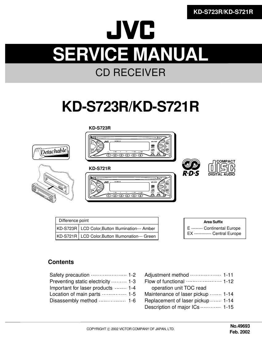
Jvc KDS 721 R Service Manual
This is the 49 pages manual for Jvc KDS 721 R Service Manual.
Read or download the pdf for free. If you want to contribute, please upload pdfs to audioservicemanuals.wetransfer.com.
Extracted text from Jvc KDS 721 R Service Manual (Ocr-read)
Page 1
KD-S723R/KD-S721 R
JVB
SERVICE MANUAL
CD RECEIVER
KD-S723R/KD-S721 R
KD-S723R
@ [flfigfi
DIGITAL AUDIO
Difference point Area Suffix
KD-S723R LCD Color,Button Illumination Amber E -------- Continental Europe
KD-S721R LCD Color,Button lllumonationm Green EX ____________ Central Europe
Contents
Safety precaution -------------- 1-2 Adjustment method ---------- 1-11
Preventing static electricity --------- 1-3 Flow of functional --------------------- 1-1 2
important for laser products ------- 1-4 operation unit TOC read
Location of main parts --------------- 1-5 Maintenance of laser pickup ------- 1-14
Disassembly method ---------------- 1-6 Replacement of laser pickup ------- 1»14
Description of major le ------------ 1-15
COPYRIGHT (2;) 2002 VICTOR COMPANY OF JAPAN, LTD. N04969:;
Feb. 2002
Page 2
KD-S723 R/KD-S72I R
Safety precaution
A CAUTION Burrs formed during molding may be left over on some parts of the chassis. Therefore,
pay attention to such burrs in the case of preforming repair of this system.
A CAUTION Please use enough caution not to see the beam directly or touch it in case of an
adjustment or operation check.
1-2
Page 7
KD-S723R/KD-S721 R
CN501
Main amplifier board
I Removing the main amplifier board
(See Fig.5 and 6)
1. Remove the front chassis.
2. Remove the bottom cover.
3. Remove the two screws B attaching the main
amplifier board assembly on the bottom of the body.
4. Remove the three screws C attaching the main
amplifier board assembly on the back of the body.
5. Disconnect connector CN501 on the main amplifier
board assembly from the CD mechanism assembly.
CD mechanism assembly
I Removing the CD mechanism assembly
(See Fig.7)
1. Remove the front chassis.
2. Remove the bottom cover.
3. Remove the main amplifier board assembly. TOP cover
4. Remove the three screws D attaching the CD
mechanism assembly from the top cover.
l Removing the control switch board
(See Fig.8 and 9)
1. Remove the front chassis.
2. Remove the four screws E attaching the rear cover
on the back of the front panel unit. E
Fig. 8 E
3. Remove the control switch board from the front
panel unit. Control switch board
1-7
Page 10
KD-S723 R/KD-S721 R
l Removing the feed motor assembly
(See Fig.10)
- Prior to performing the following procedure, remove
the CD mechanism control board, the front bracket
(loading motor) and the CD mechanism assembly.
1. Remove the two screws F and the feed motor
assembly.
lRemoving the pickup unit
(See Fig.10 and 11)
- Prior to performing the following procedure, remove
the CD mechanism control board, the front bracket
(loading motor), the CD mechanism assembly and
the feed motor assembly.
1. Detach the FD gear part of the pickup unit upward.
Then remove the pickup unit while pulling out the
part i of the FD screw.
ATTENTION: When reattaching the pickup unit,
reattach the part i of the pickup unit,
then the part i of the FD screw.
2. Remove the screw G attaching the nut push spring
plate and the pickup mount nut from the pickup unit.
Pull out the FD screw.
I Removing the spindle motor
(See Fig.12 and 13)
- Prior to performing the following procedure, remove
the CD mechanism control board, the front bracket
(loading motor), the CD mechanism assembly and
the feed motor assembly.
1. Turn up the CD mechanism assembly and remove
the two springs k on both sides of the clamper arms.
Open the clamper arm upward.
2. Turn the turn table, and remove the two screws H
and the spindle motor.
FD screw Part i
Feed motor assembly
FD gear Pickup unit
Fig.10
g-G
W
&\ Pickup mount nut
Pickup unit
Nut push spring plate
FD screw
Fig.11
Spindle motor H
Page 17
2.Pin function (2/2)
UPDI7807BGF7561
KD-S723R/KD-S721 R
:73 Symbol l/O FUNCTION
46 GNDPLL -
47 AMEQ O PLL error output for AM
48 FMEQ O PLL error output for FM
49 lC(VPP) - Setting to write for flash
50 RESET | System reset
51 SW1 l CD mech switch
52 REMOCON I Remocon input
53 NC - Non connection
54 TEL_MUTE O TEL mute output
55 POWER 0 Power control
56 CDON 0 CD power control
57 MUTE O Mute control
58 STAGE 1 -
59 BUZZER - Non connection
60 STAGE 2 -
61 ~68 NC - Non connection
69 LMO 0 CD mech driver control
70 LM1 0 CD mech driver control
71 BUCK 0 CD LSI communication line
72 CCE 0 CD LSI communication line
73 BUSO l/O CD LSI communication line
74 BUS1 l/O CD LSI communication line
75 BUSZ l/O CD LSI communication line
76 BUS3 l/O CD LSI communication line
77 RST 0 CD LSI communication line
78 PS1 | ACC detection input
79 PS2 | Memory detection
80 DETACH | Detach detection
81 RDSSCK | Clock input for RDS
82 GND1 - Connect to GND
83 MONO O Mono by force
84 SEEK/STOP 0 Switching SEEK & STOP
85 FM/AM 0 Band switch
86 AFCK O AFcheck output
87 RDSDATA l RDS data input
88 PLLMONlTOR - Non connection
89~98 NC - Non connection
99 VDDPORT - Vdd
100 GNDPORT - Connect to GND