Jvc KDS 550 Service Manual

This is the 64 pages manual for Jvc KDS 550 Service Manual.
Read or download the pdf for free. If you want to contribute, please upload pdfs to audioservicemanuals.wetransfer.com.

Page: 1 / 64
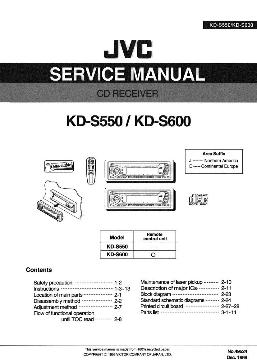
Jvc KDS 550 Service Manual

Extracted text from Jvc KDS 550 Service Manual (Ocr-read)


Page 1

KD-8550/KD-S6OO

. SERV CEWNUM

KD-35T50I KD-SGOO

Area Suffix

J ----- Northern America
E ----- Continental Europe


COMPACT
DIGITAL AUDIO
Remote
MOdel control unit
KD-SSSO --
KD-ssoo 0
Contents
Safety precaution ----------------------- 1-2 Maintenance of laser pickup --------- 2-10
Instructions ----------------------- 1-3~13 Description of major ICs ------------- 2-11
Location of main parts ----- 2-1 Block diagram --------------------------- 2-23
Disassembly method 2.2 Standard schematic diagrams -------- 2-24
Adjustment method -------------------- 2-7 Printed Circuit board ------------------ 2-27~28
Flow of functional operation Parts list ----------------------------------- 3-1 ~1 1

until TOC read ---------- 2.3

This service manual is made from 100% recyolad paper. "0.49524
COPYRIGHT© 1999 VICTOR COMPANY OF JAPAN, LTD
Dec. 1 999

Page 2

KD-SS5OIKD-8600

Safety precaution

A CAUTTON Burrs formed during molding may be left over on some parts of the chassis. Therefore,
pay attention to such burrsin the caseof pretorming repair of this system.

A CAUHON Please use enough caution not to seethe beam directly or touch it in case of an
adjustment or operation check.

Page 18

KD-SSSO/KD-SSOO

Damper bracket

- Prior to disassembling the CD mechanism, remove CD'mecmmsm assy I I
the following pans. m ;


- The front panel unit and the front chassis (Refer to
Fig.1 and 2)

. The heat sink (Refer to Fig.3)

- The bottom cover (Refer to Fig.4)

CD mechanism

- The main amplifier board (Reler to Fig.5 and 6) control board

- The CD mechanism ass'y (Refer to Fig.7) F g i

Fig.1O
IRemoving the CD mechanism control
board(See- Fig.10 and 11) Pickup unit

Flexible wire

1. Unsolder the part f and g on the CD mechanism
control board.

_ , . Shift the lock
2. Remove the stator flxmg the CD mechanism control

board and the damper bracket (To remove the stator
smoothly, pick up the center pan).

Remove the screw F attaching the CD mechanism
control board.

Remove the CD mechanism control board in the
direction of the arrow while releasing it from the two
damper bracket slots i and thetront-bracket slot j.

Disconnect the flexible wire from/connector on the
pickup unit.

ATTENTION: Turn the FD gear in the direction of the
arrow to move the entire pickup unit to
the appropriate position where the
flexible wire of the CD mechanism unit
can be disconnected easily (Refer to
Fig.11).

Pull outward I + Front bracket Pull outward

Fig.13

2-4

Page 29

3.Pin function

KD-SSSO/KD-SGOO

Pin no. Symbol Function
1 RESET lf VDD voltage becomes 4V or less.RESET output becomes low level.
This output voltage is approximately 0.5V lower than VCC. and max
2 EXT output
output current is 300mA.
A volta e su I for ACC block. This out ut volta e is a roximatel
3 COMP output 9 PP Y D 9 DD V
0.7V lower than VDD'S. The max output current is 100mA.
4 ACC Control of the COMP output by inputting voltage.
This output voltage is 5.7V, and max output current is 100mA.
5 VDD output This voltage supply is for microcomputer. Whenever back up voltage
supply is connected, the output keeps on running.
This output voltage is am, and max output current is 500mA.
6 AUDIO output
This voltage supply for AUDIO.
This output voltage is 8.0V, and max output current is 1A.
7 CD output _
ThIS voltage supply for CD.
CTRL Output selector of CD. AUDIO, lLM and EXT.
VCC To be connected with the BACK UP of car.
This output voltage is 10V, and max output current is 500mA.
10 lLM output _ _
Output voltage IS adiustable.
11 NC No use
12 GND Ground

2-15