Jvc KDLX 330 Service Manual
This is the 32 pages manual for Jvc KDLX 330 Service Manual.
Read or download the pdf for free. If you want to contribute, please upload pdfs to audioservicemanuals.wetransfer.com.
Extracted text from Jvc KDLX 330 Service Manual (Ocr-read)
Page 1
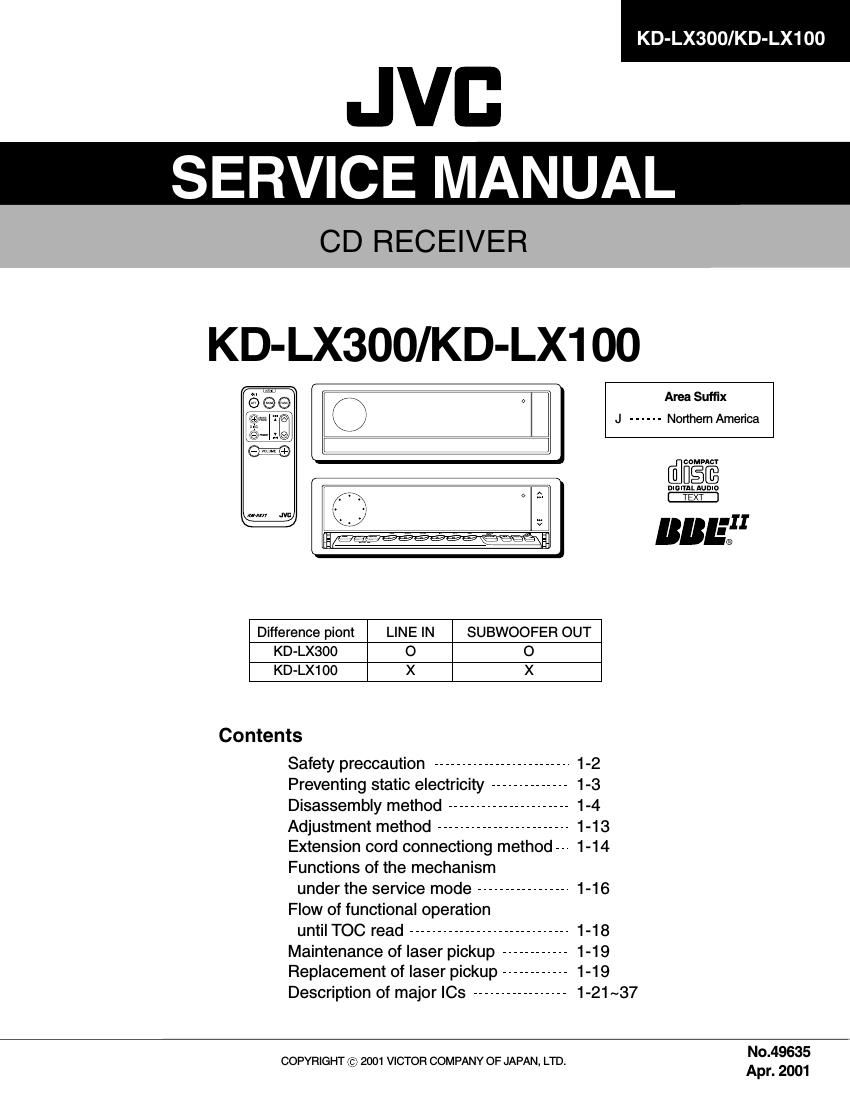
KD-LX300/KD-LX100
JVB
SERVICE MANUAL
CD RECEIVER
KD-LX300/KD-LX1 00
J ------ Northern America
Area Suffix
cuMpncr
DIGIYAL Aunla
TEXT
BB :11
Difference piont LINE IN SUBWOOFER OUT
KD-LX300 o o
KD-LX100 X X
Contents
Safety preccaution ------------------------- 1-2
Preventing static electricity -------------- 1-3
Disassembly method ---------------------- 1-4
Adjustment method ------------------------ 1-13
Extension cord connectiong method-- 1-14
Functions of the mechanism
under the service mode ----------------- 1-16
Flow of functional operation
until TOC read ----------------------------- 1-18
Maintenance of laser pickup ------------ 1-19
Replacement of laser pickup ------------ 1-19
Description of major le ----------------- 1-21 ~37
No.49635
COPYRIGHT c 2001 VICTOR COMPANY OF JAPAN, LTD.
\ Apr. 2001
Page 2
Description of major le
I FAN8037 (IC661) : CD driver
1. Pin layout & Block diagram
2. Pin function
KD-LX300/KD-LX100
Pin
5i: Symbol l/O Function ND. Symbol l/O Function
1 |N2+ l CH2 op-amp input(+) 25 DO7+ 0 CH7 drive output(+)
2 |N2- l CH2 op-amp input(-) 26 006- 0 CH6 drive output(-)
3 OUT2 0 CH2 op-amp output 27 D06+ 0 CH6 drive output(+)
4 |N3+ | CH3 op-amp input(+) 28 PGND2 - Power ground2
5 |N3- l Ch3 op-amp input(-) 29 DOS- 0 CH5 drive output(-)
6 OUT3 0 CH3 op-amp output 30 D05+ 0 CH5 drive output(+)
7 |N4+ l CH4 op-amp input(+) 31 004- 0 CH4 drive output(-)
8 |N4- l CH4 op-amp input(-) 32 DO4+ 0 CH4 drive output(+)
9 OUT4 0 CH4 op-amp output(+) 33 003- 0 CH3 drive output(-)
10 CTL1 l CH5 motor speed control 34 D03+ 0 CH3 drive output(+)
11 FWD1 l CH5 forward input 35 PGND1 - Power ground1
12 REV1 I CH5 reverse input 36 002- 0 CH2 drive output(-)
13 CTL2 | CH6 motor speed control 37 DO2+ 0 CH2 drive output(+)
14 FWD2 l CH6 forward input 38 001- 0 CH1 drive output(-)
15 REV2 l CH6 reverse input 39 DO1+ 0 CH1 drive output(+)
16 SGND - Signal ground 40 PVCC1 - Power supply voltage
17 FWD3 | CH7 forward input 41 REGOX l Regulator feedback input
18 REV3 l CH7 reverse input 42 REGX O Regulator output
19 CTL3 l CH7 motor speed control 43 RESX l Regulator reset input
20 SB I Stand by 44 VREF l Bias voltage input
21 PS I Power save 45 SVCC - Signal supply voltage
22 MUTE I All mute 46 |N1+ l CH1 op-amp input(+)
23 PVCC2 - Power supply voltage 47 |N1- l CH1 op-amp input(-)
24 D07- 0 CH7 drive output(-) 48 OUT1 0 CH1 op-amp output
1-21