Jvc KDGS 770 Service Manual

This is the 60 pages manual for Jvc KDGS 770 Service Manual.
Read or download the pdf for free. If you want to contribute, please upload pdfs to audioservicemanuals.wetransfer.com.

Page: 1 / 60
Jvc KDGS 770 Service Manual

Extracted text from Jvc KDGS 770 Service Manual (Ocr-read)


Page 1

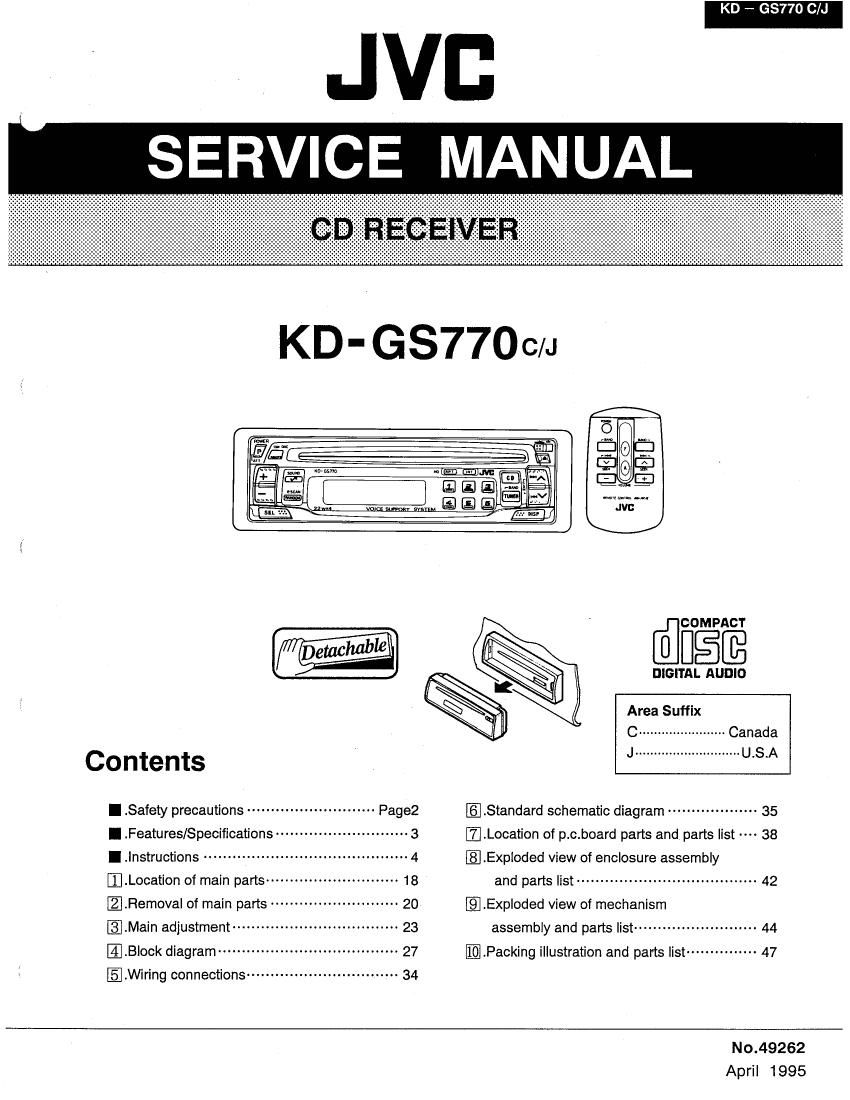
KD - GS770 C/J

Eflfiéfé

DIGITAL AUDIO

Area Suffix

C ....................... Canada

J ............................ USA

Contents
I .Safety precautions -------------------------- Page2 [E .Standard schematic diagram ------------------- 35
I .Features/Specifications I.Location of p.c.board parts and parts list 38
I .lnstructions ----------------------------------------- 4 I.Exploded view of encIosure assembly
I.Location of main parts ............................ 1g and parts list ...................................... 42
I.Removal of main pads ~ @Exploded view of mechanism
I.Main adjustment ................................... 23 assembly and parts list .......................... 44
I.Block diagram ...................................... 27 [Packing illustration and parts list ............... 47
.Wiring connections ................................ 34
No.49262

April 1995

Page 2

KD - GS770 C/J

lSafety Precautions

J (USA) Only
important for Laser Products

1. CLASS 1 LASER PRODUCT

2. DANGER: Invisible laser radiation when open and in-
terlock failed or defeated. Avoid direct exposure to beam.

3. CAUTION: Do not open the bottom cover. There are no
user serviceable parts inside the unit; leave all servicing
to qualified service personnel.

4. CAUTION: The compact disc player uses invisible laser
radiation and is equipped with safety switches which pre-
vent emission of radiation when unloading cartridge and
the safety interlocks have failed or are defeated. It is
dangerous to defeat the safety switches.

5. CAUTION: Use of controls of adjustments or perfor-
mance of procedures other than those specified herein
may result in hazardous radiation exposure.

6. CAUTION: The laser is able to function, if safety swit-
ches are out of function. The laser light is invisible, avoid
exposure, do not disassemble the laser unit, but replace
the complete unit.

Identification And Certification Labels

Bottom panel of the main unit
Pane inferior de la unidad principal
Panneeu inférieur do I appaleil principal

U5 JVC CORP. 41 SLATER DRiVE
ELMWOOD PARK, NJ. 07407
MANUFACTURED AT

MADE IN 7-

Product compies with DHHS Flutes 21
CFR Subchapter J in effect at date of
manufacture.
MANUFACTURED

'1

Notes: NAM
'i The date of manufacture. E/RATING PLATE

2 The in code of manufacturing plant.
'3 Marking of country origin.

2 (No. 49262)

Page 22

KD - GS770 C/J

- - connector choard
EggrfigllnagqgesgD $3330" 1: conductor F.P.C.cable (from the pickup)
1. Remove the bottom plate. 4-mnduc®°r%£fitfi3béfi:kup)
2. Remove the CD mechanism assembly. 0 0
3. Place the CD mechanism assembly to expose the 3 pickup shamg
bottom side upward. Remove screw (D retaining pickup J
shaft ® to remove it together with the shaft holder. 1
4. Loosen screw ® retaining pickup shaft ® at the other Shaft holder
end. Remove two screws ® retaining pickup shaft ®. ® 7 G)
5. Disconnect the 11-conductor F.P.C. cable and the [E ,
Pickup shaft ®
9

4-conductor F.P.C. cable, respectively, from the CD
mechanism control relay P.C. board.

6. Take the CD pickup unit out of the CD mechanism 5 n hi "1 t
assémby- w c @ a Feed motor

0 Cautions for removal and assembly

1. To disconnect the 11-conductor and 4-conductor F.P.C.
cables, first pull the connectors in the directions of J
arrows as shown in Fig. 2- 8. S .

2. When reassembling, arrange the 11- conductor and 0 6/ 0.- \ U
4-conductor F.P.C. cables as shown in Figs. 2- 8 to Wading WW
2, 10.

O Removing the feed motor and the loading motor Fig. 2 - 7
assembly

1. Remove three screws ® retaining the switch P.C. board
from the CD mechanism assembly.

2. Push two hooks and retaining the switch P.C.
board in the respective direction of arrows to disengage
the P.C. board from the hooks.

3. Remove screw ® retaining the feed motor.

4. Remove screw 01) retaining the loading motor.

5. Lift the switch P.C. board slightly upward and unsolder
the blue and pink wires connected to the feed motor
from the switch P.C. board.

6. Unsolder the red and black wires connected to the
loading motor from the switch P.C. board. Connworpfimm

11- conductor connector

4- con. uctor connector

11- conductor F.P.C.cable 4- conductor F.P.c.cable

Fi . 2 ~ 8

When feeding the F.P.C. cable through the holder after 9

replacement of the pickup is complete, insert a thin film

together with the cable to help It slide along the film in

the direction of the arrow, then set it as shown in

Fig. 2- 9.

If you fall to set It by following this procedure,

disassemble the mechanism, then reassemble it.

11- conductor F.P C.cable
4- conductor F.P.C. cable

Thin film

1 (for use as a iig)
\1

\f

Splndle motor


Plckup unit

II-pin connector F.P.C.cable
Fig. 2 - 10 (for the Pickup unit) Fig.2 - 9

22 (No. 49262)

Page 58

KD - GS770 C/J

BLOCK N0.IIMI I

A Rl-Zl". IARIS NO PARTS NAME REMARKS QTY SUFFIX CLR
77 61.020415T SW. 1
78 681402156T CONNECTOR 2
79 681402158T CONNECTOR 1
80 68150225T CONNECTOR 1
81 68150226T CONNECTOR 1
82 68170211T CONNECTOR 1
83 68210102T CONDENSOR 1
86 30301101T LOADING GEAR(A) 1
87 30301102T LOADING GEAR(B) 1
88 30301103T LOADING GEAR(C) 1
89 30301104T LOADING GEAR(D) 1
90 30301105T L CLUTCH DISC 1
91 30301108T CAM GEAR 1
92 30301109T LOAD.GEAR PLATE 1
93 30301110T SELECT LEVER 1
100 9B1220051T TAPPING SCREW M2 X 5 S
101 9C0420253T TAPPENG SCREW M2 X 2.5 3
102 9P0420041T SCREW(M2 X 4) M2 X 4 2
103 9C0117223T SCREW M1.7 X 2.2 2
104 9C2220603T TAP.SCREW M2 X 6 8
105 9C3720803T TAP.SCREW M2 X 8 1
106 9C3920013T TAP.SCREW M2 X 11 4
107 9P0220041T TAMS SCREW M2 X 1+ 2
108 9C3817403T TAP.SCREW M1.7 X 4 4
109 9C0117225T CAMERA SCREW 2
110 9P1220051T S TAPPING SCREW 2 X 5 2
130 303005301T FEED MOTOR ASY. 1
131 303005302T SPIN.MOTOR ASY 1
132 303005303T FEED SCREW ASY. 1
133 303011301T LOAD.MOTOR ASY. 1
134 303010301T CONNECTOR BOARD 1

46 (No. 49262)