Jvc KDGS 50 Service Manual

This is the 64 pages manual for Jvc KDGS 50 Service Manual.
Read or download the pdf for free. If you want to contribute, please upload pdfs to audioservicemanuals.wetransfer.com.

Page: 1 / 64
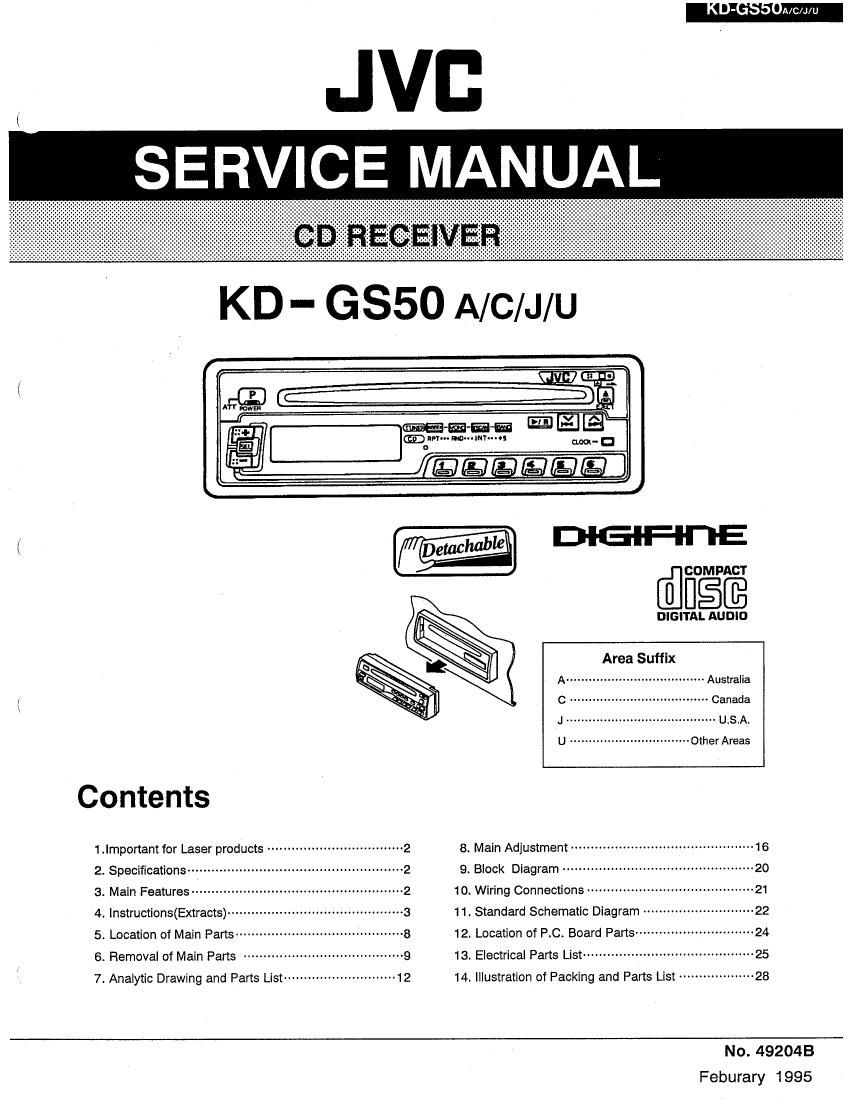
Jvc KDGS 50 Service Manual

Extracted text from Jvc KDGS 50 Service Manual (Ocr-read)


Page 1

' I O

JVB
SERVICE MANUAL

KD - GSSO A/C/J/U

up". "am...
we r N cum-D

DIG-lF-I-l'lE

{,
@COMPACT
DIGIQLSNJELE
Area Suffix
A" - Australia
{ C . -~ Canada
J -~ u.s.A.
U ................................ Other Areas
Contents
1 _|mponam for Laser products .................................. 2 8. Main Adjustment .............................................. 15
2. Specifications ------------------------------------------------------ 2 9_ Block Diagram ................................................ 20
3. Main Features ~~~~~~~~~~~~ 10. Wiring Connections ---------------------- ---21
4. lnstructions(Extracts)- 11. Standard Schematic Diagram -------- "-22
5. Location of Main Parts- 12. Location of RC. Board Parts ---------------------------- 24
5_ RemOVa| of Main Parts ........................................ 9 13. Eiecmcal Pans List ............................. ...25
7- Anaiytic Drawing and Parts List -------------------------- 12 14, Illustration of Packing and Parts List ----- v---23

No. 492043
Feburary 1995

Page 2

KD-GS50A/cu/u

1. Precautions

lMPORTANT FOR LASER PRODUCTS Identification And Certification Labels
(For U.S.A. only) Bottom panel oi the main unit

Precautions

1. CLASS 1 LASER PRODUCT

2. DANGER: Invisible laser radiation when
open and interlock tailed or detected. Avoid

US JVC CORP tli SLATER DRIVE

direct exposure to beam. ELMWOOD PARK, it J 07' 07
3. CAUTION: Do not open the top cover. There MANUFACTURED Ai _
are no user-serviceable parts inside. Leave MfiQE '

all servicing to qualified service personnel.
4. CAUTION: This CD player uses invisible

Promtct complies wmt DHHS Ru - 5i

cm Sillmhuplcr J ill client at dart:- oi

laser radiation. however. is equipped with
saiety switches to prevent radiation emission
when unloading 00s. it Is dangerous to
defeat the safety switches.

5. CAUTION: Use oi controls. adjustments or
performance at procedures other than those
specified herein may result in hazardous
radiation exposure.

2. Speacifications

CD PLAYER SECTION

Type: Compact disc player

Signal Detection System: Noncontact optical pickup
(semiconductor laser)

Number oi Channels: 2 channels (stereo)

Frequency Response: 5 to 20.000 Hz

Dynamic Range: 95 dB

Signal-to-Noiae Ratio: 97 :13

Wow a Ftulter: Less than measurable limit

AUDIO AMPLIFIER SECTION

Maximum Power Output: (Front) 22 W per channel
(Rear) 22 W per channel

Continuous Power Output (EMS): (Front) 8 W per
channel into 4 n, 40 to 20,000 Hz at no more than
0.6% total harmonic distortion. (Rear) 3 W per
channel into 4 n. 40 to 20,000 Hz at no more than
0.0% total harmonic distortion.

Load impedance: 4 fl (4 to B Q allowance)
Tone Control Flange

Bass: tlo dB at 100 Hz

Treble: :10 dB at 10 kHz
Frequency Response: 40 to 20.000 Hz
Signal-to-Noise Ratio: 70 dB
Line-Out Level: 1.5 Vl20 kn load (Full scale)
Output Impedance: 1 kn

RADIO SECTION
Frequency Flange
FM: 87.5 to 107.9 MHz
(with channel Interval set to 200 kHz)
87.5 to 108.0 MHz
(with channel interval set to 100 kHz)
AM: 530 to 1,710 kHz
(with channel interval set to 10 kHz)
531 to 1,602 kHz
(with channel interval set to 9 kHz)
[FM Tuner}
Usable Sensitivity: 12.1 d8t( I.~t uvns n)
50 (13 Quietan Sensitivity: 16.3 dB! (1.8 itV/75 n)
Alternate Channel Selectivity: (400 kHz): 65 dB
Frequency Response: 40 to 15,000 Hz
stereo Separation: 35 dB
Capture Ratio: 2.0 dB
(AM Tuner]
Sensitivity: 20 W
Selectivity: 35 as

2 (No. 492048)

mamiidcitirfl

NAMEIFIATING PLATE

Notes:

1 The date oi manuiacture.

MANUFACTURED

'2 The in code oi manufacturing plant.

3 Marking oi country origin.

GEN ERAL

Power Requirement
Operating Voltage: DC 144 volts lit to 16 volts
allowance)
Grounding System: Negative ground

Dimensions (W x H x D) Installation Size: 178 x 50 x
159 mm (7-1/16" x 2 x 6-5/16")
Panel Size: 190 x 58 x 18 mm (7-1/2" x 2-5/16" x
3/4").

Gross Weight: 2.1 kg (4.7 lbs)

Design and specifications sub/ear to change without
notice.

3. Main Features

0 Detachable Control Panel

0 Direct-in" disc loading system

0 Direct Access Play/Skip Play/Search Piayl
Repeat Play/Random Play/intro Play

0 High Sensitivity Tuner

0 AMIFM Stereo PLL Synthesizer Tuner

0 24-Stetlon Preset Tuning (FM-1B, AM-6)

0 Preset Scan/SeeldManuai Tuning

0 4-Channei Amplifier System

0 Maximum Power Output oi 22 watts per
channel (Front)/22 watts per channel (Rear)

0 Digital Clock Display

0 Line Output Terminal

/\(

Page 29

KD'GSSOA/C/J/U

I CD Section
lteme Conditions Adjustment and Confirmation Standard Value Adjusting
1. TOC check Oscilloscope 1. Confirm lighting illumination by power on.
2. Not to occur unclear indication and uneven lighting
of LCD.
2. AF level Measuring Instruction 1. Connect the oscilloscope between TP1 and Within
(eye-pattern) Oscilloscope TP2 to confirm that peak~to-peak value of 1.5V i 300mV

check

eye~pattern waveform is within 1.5V i SOOmV

Eye pattern waveform

Wigs; -

i.

it!!!

N.

ltt\\.

This amplitude should
be maximum and the
waveform clear.

Fig.8~5

3. Tracking
offset
adjustment

Measuring instruction
Oscilloscope

Adjustment procedure

1. Connect the oscilloscope between TP2 and
TP3 .

2. Play back the disc.

3. Shot circuit TP2 and TP4.

4. ddjust VR501 so that the DC level of the
tracking error signal (oscilloscopee
waveforme) becomes zero.
when the tracking offset meter is used for
measurement, it shorld read "0" (zero).
Note : Adjust VR501 so that the waveform is

vertically symmetric about the zero
level. use a direct coupling oscilloscope

ill
W

Tracking offset wave

zero level

form

VR501

Set the P-P
center of
the DC level
to zero.

Flg.8~6

4.0utermost

1 . Directly access the outer circumference track

circumference 31, check that play is performed normally
and that abnormalities including sound
jumping do NOT occur.
5. Outer to 1. Skip from the outer circumference track 24
Inner (also possible wlth other dlscs outermost
clrcumferenc circumference) to track 1' and check the time

till play starts. Normally It is less than 5
seconds.

(No. 492048) 25

Page 32

KD'GSSONC/d/U

9. Wiring Connections

____,

CD Mechanism relay board
@ Spindle motor
CD Mechanism control switch board [I
O O
O
O

f0 Dee «ata-
i

I

7 l

J

l
Loading motor :


4363

O

2

Feed motor

Maln amplifier board 13 pin connector

V
_!
Ii CJ35I .
: Llne out lack CN901
j CN50| -
FM/AM tuner pack I
_l CN502 -
_.I

CN60I
Color codes are shown bolow.

1 .
2
3
Antenna socket 1;
LCD operation switch board 6
0 III] 7
o O cueou s
9
,0

D .

Fig. 9-1 C ........... Light Blue

28 (No 492048)