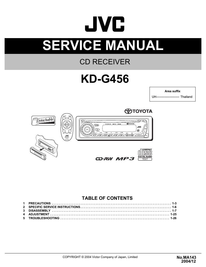
Jvc KDG 456 Service Manual
This is the 129 pages manual for Jvc KDG 456 Service Manual.
Read or download the pdf for free. If you want to contribute, please upload pdfs to audioservicemanuals.wetransfer.com.
Extracted text from Jvc KDG 456 Service Manual (Ocr-read)
Page 1
1-2 (No.MA143) SPECIFICATION Design and specifications are subject to change without notice.AUDIO AMPLIFIER SECTION Maximum Power Output Front 50 W per channel Rear 50 W per channel Continuous Power Output (RMS) Front 19 W per channel into 4 Ω 40 Hz to 20 000 Hz at no more than 0.8% total harmonic distortion. Rear 19 W per channel into 4 Ω 40 Hz to 20 000 Hz at no more than 0.8% total harmonic distortion. Load Impedance 4 Ω (4 Ω to 8 Ω allowance) Tone Control Range Bass ±10 dB at 100 Hz Treble ±10 dB at 100 Hz Frequency Response 40 Hz to 20 000 Hz Signal-to-Noise Ratio 70 dB Line-Out Level/Impedance 2.0 V/20 kΩ load (full scale) Output Impedance 1 kΩ Output terminals CD changer TUNER SECTION Frequency Range FM 87.5 MHz to 108.0 MHz AM 531 kHz to 1 602 kHz FM Tuner Usable Sensitivity 11.3 dBf (1.0 µV/75 Ω) 50 dB Quieting Sensitivity 16.3 dBf (1.8 µV/75 Ω) Alternate Channel Selectivity (400 kHz) 65 dB Frequency Response 40 Hz to 15 000 Hz Stereo Separation 35 dB Capture Ratio 1.5 dB AM Tuner Sensitivity 20 µV Selectivity 35 dB CD PLAYER SECTION Type Compact disc player Signal Detection System Non-contact optical pickup (semiconductor laser) Number of channels 2 channels (stereo) Frequency Response 5 Hz to 20 000 Hz Dynamic Range 96 dB Signal-to-Noise Ratio 98 dB Wow and Flutter Less than measurable limit MP3 decoding format MPEG 1/2 Audio Layer 3 Max. Bit Rate: 320 Kbps GENERAL Power Requirement Operating Voltage DC 14.4 V (11 V to 16 V allowance) Grounding System Negative ground Allowable Operating Temperature 0°C to +40°C Dimensions (W × H × D) Installation Size (approx.) 182 mm × 52 mm × 150 mm Panel Size (approx.) 188 mm × 58 mm × 11 mm Mass (approx.) 1.4 kg (excluding accessories)
Page 2
(No.MA143)1-3 SECTION 1 PRECAUTIONS 1.1 Safety Precautions ! Burrs formed during molding may be left over on some parts of the chassis. Therefore, pay attention to such burrs in the case of preforming repair of this system. ! Please use enough caution not to see the beam directly or touch it in case of an adjustment or operation check.