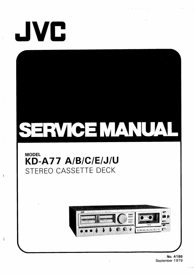
Jvc KDA 77 Service Manual
This is the 40 pages manual for Jvc KDA 77 Service Manual.
Read or download the pdf for free. If you want to contribute, please upload pdfs to audioservicemanuals.wetransfer.com.
Extracted text from Jvc KDA 77 Service Manual (Ocr-read)
Page 1
KD-A77A/8/C/E/J/U r- Contents Specifications ......................................................... 2 Features .................................................................. 3 Controls and Connections .......................................... 3 Main Parts Location ................................................... 4 Maintenance ............................................................ 4 New Technique ...................................................... 5 Removal of the Main Parts .......................................... 6 Main Adjustments ................................................... 1 0 Block Diagram ...................................................... 16 Integrant Circuit ...................................................... 18 Standard Schematic Diagram of KD-A 77 Amplifier circuit ................................................ 1 9 Mecha. control circuit .......................................... 20 Wiring Connection (1 ) of KD-A 7 7 .............................. 21 Specifications Type Track system Tape speed Frequency response OVU Metal tape SA/Cr02 tape -20VU Metal tape SA/Cr02 tape * 1 *2 SF/Normal tape * 3 SIN ratio Stereo cassette deck 4-track, 2-channel 1-7/8 inch/sec (4.8 cm/sec) 25-12500Hz ±3dB(Typical) 25 -8000Hz ± 3dB(Typical) 15-20000Hz 25 -1 8000Hz ± 3dB(Typical) 15-20000Hz 25- 1 8000Hz ± 3dB(Typical) 15-19000Hz 25-17000Hz ±3dB(Typical) Surpases DIN 45 500 60dB (from peak level, weighted, Metal tape) The SIN is improved by 5dB at 1 kHz and by 10dB above 5kHz with ANRS on. (DIN 45 500 weighted) Effect of Super ANRS : (normal tape) Improvement of SIN : the same as with ANRS Improvement of frequency response : OVU recording; 6dB at 10kHz + 5VU recording; 12dB at 10kHz Improvement of distortion Wow and flutter Crosstalk Hormonic distortion Bias Erasure Heads No.4186 OVU recording; 3 % or less at 10kHz + 5VU recoridng; 3 % or less at 10kHz 0.04% (WRMS), 0.14% (DIN 45 500) 65dB (1 kHz) K3; 0.4%, THD: 1.0% (metal tape, 1 kHz OVU) AC bias (85kHz) AC erasure (85kHz) 3 heads SEN ALLOY head for recording, SEN ALLOY X cut type for playback and two-gap SEN ALLOY head for erasure Wiring Connection (2) of KD-A77 .............................. 22 Enclosure Ass'y and Electrical Parts ........................... 25 Enclosure Ass'y and Electrical Parts List .................. 23 Mechanical Components Parts ................................. 26 Mechanical Components Parts List ........................ 28 Printed Wiring Board Parts Main Amp. P.W. Board Parts .................................... 33 Power Supply P.W. Board Parts ................................. 34 Main Amp. P. W.B Parts List ................................. 30 Power Supply P.W.B Parts List .............................. 35 Other P.W.B Parts ................................................... 37 Other P. W.B Parts List ....................................... 39 Packing ...................................................... Back cover Accessories ................................................ Back cover Motors Fast forward time Rewind time Semiconductors Input terminals Output terminals Power requirement Power consumption Dimensions Weight FG type DC servo motor (for Capstan) DC motor (for Reel) 85 sec. with C-60 cassette 85 sec. with C-60 cassette 1 8 ICs, 49 transistors, 59 diodes, 14 LEDs Mic jack x 2, Max. sensitivity; 0.2mV (-72dBs) Matching impedance; 6000-10kO Input jack x 2, Min. input level; 80mV (-20dBs) Input impedance; 100kO Output jack x 2, Output level; 0-300mV Output impedance; 6kO Matching impedance: 50kO or more Phones jack x 1, Output level; 0-0.5mW/SO Matching impedance: 80-1 kO AC 120V, 60Hz (KD-AnCW AC 240/220/120V, 50/60Z (KD-A n A/B/E) AC 240/220/120/1 OOV, 50/60Hz (KD-A77U) 36W 17-3/4" (450 mm) W 4-3/4" (120 mm) H 12-7/16" (316mm)D 18.3 Ibs (8.3 kg) Note: * 1 ... SCOTCH MET AFINE or Equivalent * 2 ... TDK SA or Equivalent * 3 ... MAXELL UD or Equivalent Design and specifications are subject to change without notice. - 2 -
Page 2
Features 1. 3 SA (SEN-ALLOY) heads Combined SA (SEN-ALLOY) record/play (X-cut type) heads make possible record monitoring. The erase head is a 2-gap head also made from SA (SEN-ALLOY). 2. Two-motor ID (independent Drive) mechanism This mechanism incorporates a newly developed Back Tension system which gives improved tape contact with the head. 3. Self-illuminated buttons for full logic mechanical operation (excluding STOP or REC-MUTE modes.) 4. Three position Metal-Tape-Compatible tape select switch. METAL -FeCr _ SA/Cr02 NORM (Automatic switching between SA/Cr02 and NORM) 5. The REC MUTE button is at the right side of the mechanical operation buttons. KD-An A/B/C/E/J/U 6. ANRS which reduces tape hiss to an inaudible level and Super ANRS which improves linearity at high fre quencies are incorporated. 7. MEMORY/AUTO REW switch 8. Recording equalizer switch 9. Timer standby capability for automatic recording or playback using an AC timer. 10. Geared and oil-damped cassette holder. 11. New Metal-Tape-Compatible multi-peak level in dicators (+ 9dB, + 6dB, + 3dB, -2dB, -7dB). together with back-lit VU meters with the expanded coverage from + 7VU to -20VU, make level observa tion easier. 12. OUTPUT volume (for LINE and HEADPHONES use) 13. Remote control terminal (for the optional remote con trol unit -R-30E). Controls and Connections 2 3 4 5 6 10 11 12 14 15 16 17 18 19 20 21 == == == == == == == == == == r- == . . == '- 1. VU meters and Multi-point peak level indicators 2. INPUT LEVEL control 3. TAPE indicators 4. ANRS/Super ANRS indicators 5. Cassette holder 6. MEMORY/AUTO REW switch 7. Tape counter/counter reset button 8. EJECT button 9. TIMER STANDBY switch 10. PHONES jack 11. MIC jacks 12. INPUT SELECT switch 13. ANRS switch 14. TAPE SELECT switch 15. REC EQ switch 1 6. OUTPUT LEVEL control n LJ - 22 23 24 [f] r~:f ~1 r -[ ~ I 1 7. MONITOR switch 1 8. Cassette Operation buttons ~~ REW (rewind) button ~~ FF (fast forward) button ~ PLA Y button - STOP button o REC (record) button 11 PAUSE button REC MUTE button 19. POWER switch 20. Power cord 21. Voltage select switch (KD-A 77 A/B/E/U) 22. REMOTE CONTROL socket 23. LINE IN (REC) terminals 24. LINE OUT (PLAY) terminals - 3 - No.4186