Jvc JA S8 Owners Manual

This is the 12 pages manual for Jvc JA S8 Owners Manual.
Read or download the pdf for free. If you want to contribute, please upload pdfs to audioservicemanuals.wetransfer.com.

Page: 1 / 12
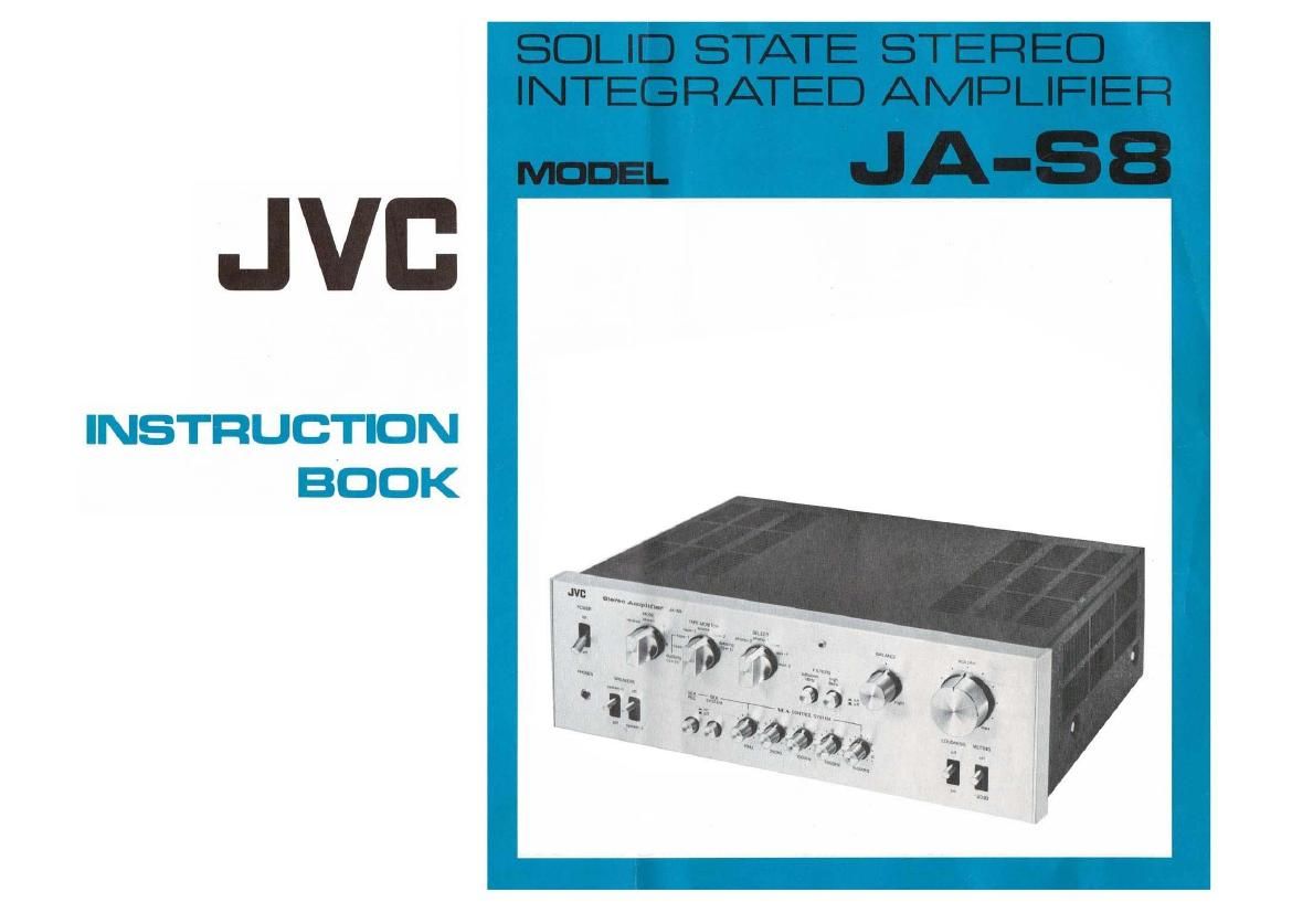
Jvc JA S8 Owners Manual

Extracted text from Jvc JA S8 Owners Manual (Ocr-read)


Page 2

FEATURES

Auto-restoring triple protection circuit for speakers and power transistors
Circuits designed for ideal transient response

S.E.A. (Sound Effect Amplifier) tone control system

S.E.A. recording and two-way dubbing facilities

All-stage direct-coupled pure complementary OCL power circuit
Low-noise NPN-PNP hybrid 2-stage direct-coupled equalizer of Darlington
connection

Effective subsonic (low) and high filters

Connects up to two pairs of stereo speaker systems

Two sets of PRE OUT terminals for convenience

4-channel adaptable design

Unique chassis layout reduces shielded wiring

@PPWNf

d-LOWN

CONTENTS

FEATURES ........................ Inside Front Cover
CAUTION NOTICE .................... Inside Front Cover
CONNECTION DIAGRAM .......................... 1
REAR-PANEL DISPLAY CALLOUTS .................... 2
FRONT-PANEL DISPLAY CALLOUTS .................... 3
TAPE RECORDlNG/PLAYBACK/DUBBING ................. 4

RECORDING ............................... 4

PLAVBACK ................................ 4

DUBBING ................................. 4

S.E.A. RECORDING ........................... 5
PRE/MAIN AMPLIFIERS ........................... 6
SPEAKER CONNECTIONS .......................... 6
4-CHANNEL CONNECTIONS ......................... 6
S.E.A. ..................................... 7
PERFORMANCE GRAPHS .......................... 8

SPECIFICATIONS ...................... Inside Back Cover

CAUTION NOTICE

0 DO NOT attempt repairs or rear-panel adjustments while AC power cord is
connected to primary AC power source.

0 DO NOT change speaker connections or attach other components while AC
power is switched on; speaker damage could result.

a DO NOT operate amplifier on a power line voltage more than 10% over
specified voltage; power transistors and other important parts may be
severely damaged.

o DO NOT use amplifier where temperature exceeds 35°C (90°F) or where
relative humidity exceeds 90%.

a DO be sure to connect inputs and speakers correctly; in case of incorrect
connections or short-circuits, reproduction may be out of phase. Unstable
sound image, or activation of protection circuit could result.

0 DO be sure to provide adequate ventilation space around amplifier in use to
protect power transistors, especially when, for some reason, square»wave
signals of continuous power over 10 watts are fed to amplifier for more than
one hour.

. When amplifier is turned on, speakers receive signals only after a few
seconds' delay. DO NOT adjust switches and controls for seven or eight
seconds after amplifier is turned on to avoid possible damage to speakers.

0 DO turn off amplifier and correct abnormalities if protection circuit is
activated. NEVER touch any part of circuit inside amplifier's chassis.
When abnormal condition is corrected, protection circuit will be automatic-
ally restored.

0 DO be sure that the pin plugs are firmly inserted into the pin jacks; this
will help prevent hum and damage to speakers.

- When two sets of stereo speaker systems are connected and driven at the
same time, the impedance of each speaker must be 8 ohms or over.

- DO follow the instructions in this Instruction Book in full before
attempting to operate amplifier.

Page 7

PRE/MAIN AMPLIFIERS

The preamplifier output and main amplifier input terminals are connected by
cables. When the cables are removed, the pre and main amplifier sections of the
JA-SB are separated and may be used independently. When the preamplifier
section is used, all the controls and switches remain live", except for the
SPEAKER switches. On the other hand, when the main amplifier is used, only
the SPEAKER switches are operative with other controls and switches
inoperative lie. the JA-SB performs as a power amplifier).

A further design advantage enables you to leave the pre/main connection cables
in place but still derive a preamplifier signal (through the second set of RPE
OUT terminals) to be fed to such special equipment as an add-on amplifier, a
separate VU meter or other measuring or testing instrument, etc. UNDER
NORMAL OPERATION CONDITIONS THE PRE/MAIN CONNECTION
CABLES SHOULD REMAIN IN PLACE.

SPEAKER CONNECTIONS

The JA-SB connects up to two pairs of stereo speaker systems (1 and 2). Either
pair can be driven independently by the SPEAKERS switches. The speaker
terminals on the rear panel are grouped under the markings 1" and "2".

Speaker connection cables from the left speaker in System 1 should be attached
to the two right-hand terminals grouped under the marking 1; and cables from
the right speaker in that System should be attached to the two left-hand
terminals grouped under 1". Accordingly, cables from the left and right
speakers in System 2 are attached to the proper terminals under the marking
2".

Care must be taken to assure that the +" cable from each speaker is attached to
the +" terminal for that speaker, and that the -" cable is attached to the "-"
terminal. improper connections ("+" to - or vice versa) will put your
speakers "out of phase" with each other and they will not respond properly. In
case of a short in speaker cables or other malfunction, the protection circuit
built into the JA-SB will activate to protect the amplifiers vital power transistors
and your speakers. When the malfunction is corrected, the circuit will restore
itself automatically.

4-CHANNEL CONNECTIONS

The JA-SB is designed to be easily integrated into a 4-channel high fidelity
system. All that is needed to complete such a system is an additional pair of
stereo speakers, another stereo integrated amplifier for the rear channels and a
4-channel source components (such as a CD4 disc demodulator, a matrix
decoder or a discrete 4-channel tape deck or cartridge player). Thanks to the
advanced 4gang VOLUME control in the JA-SB you can control the volume
(and the muting and the loudness) of all four channels when such a system is
properly connected. (See illustration below.)

NOTE: it is possible to connect the PRE OUT terminals of the second stereo
integrated amplifier to the 4-CHANNEL REAR IN terminals of the
JA-SB, and to connect the MAIN IN terminals of that amplifier to the
4-CHANNEL REAR OUT terminals of the JA-SB.
This will result in a workable 4'channel interconnection, BUT MAY
FALL T0 PRODUCE IDENTICAL SOUND VOLUMES FROM THE
FRONT AND REAR SPEAKERS IF THEIR IMPEDANCES ARE
DIFFERENT.

Volume, Mutmg and Loudness
controls become common, and
both can be controlled from this
ampliller.

F rant
Speakers


4-CHANNEL
SOURCE


Rear
5 I 9ak8rs

REAR

4-CHANNEL SOU RCE:
4-Channel Tape Deck, CD-4
Disc 4-Channel Demodulator
etc.

Add-on Power Amplifier

4-Channel System Connections