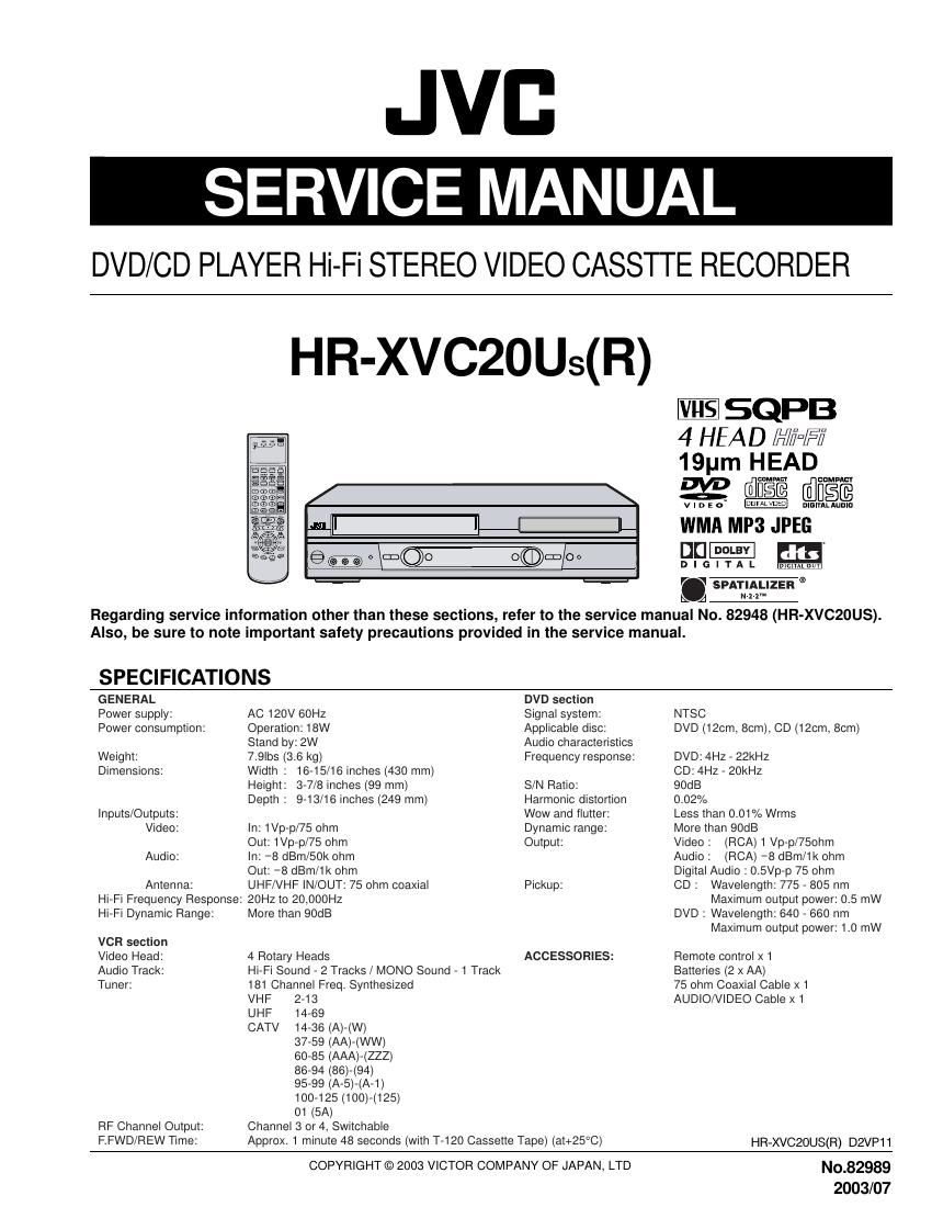
Jvc HRXVC 20 UR Service Manual
This is the 62 pages manual for Jvc HRXVC 20 UR Service Manual.
Read or download the pdf for free. If you want to contribute, please upload pdfs to audioservicemanuals.wetransfer.com.
Extracted text from Jvc HRXVC 20 UR Service Manual (Ocr-read)
Page 2
TABLE OF CONTENTS
Section Title
HOW TO IDENTIFY MODELS
DISASSEMBLV INSTRUCTIONS
1L REMOVAL OF MECHANICAL PARTS AND P.C.BOARDS
171 TOP CABINETAND FRONT CABINET
72 FLAP ........
DVD DECK
1
173
174 ..
175 VCR DECK
176
4. REMOVAL OF DVD DECK PARTS
*1 TRAY ...........................
2 MAIN CHASSIS ASS'Y ..
*3 RACK LOADING I MAIN GEAR/Fl ..
,4 CLAMPER ASSY/ |NSULATOR(R) / LEVER SWITCH
,5 TRAVERSE HOLDER / |NSULATOR(F)
*6
,7
*8
SWITCH PCB ASS'Y
RACK FEED ASSY
RELAY PCB ASSY.
49 GEAR ..
440 IDLER
4711 FEED MOTO
ELECTRICAL ADJUSTMENT PARTS LOCATION GUID
WHEN REPLACING EEPROM(MEMORY) IC
SERVO TIMING CHART ...............................
CHARTS AND DIAGRAMS
INTERCONNECTION DIAGRAM IIIIIIIIIIIIIIIIIIIIIIIIIIIIIIII
Y/C/AUDIO/CCD/HEAD AMP SCHEMATIC DIAGRAM
SYSCON SCHEMTAIC DIAGRAM .......
TUNER/JACK SCHEMATIC DIAGRAM
OPERATION/DISPLAY SCHEMATIC DIAGRAM
HIEFI/DEMODULATOR SCHEMATIC DIAGRAM
POWER SCHEMATIC DIAGRAM IIIIIIIIIIIIII
OPERATION/LED SCHEMATIC DIAGRAM
SW/RELAY/FG SCHEMATIC DIAGRAM
MPEG/MICOM SCHEMATIC DIAGRAM .
MEMORY SCHEMATIC DIAGRAM ......
RF AMP/DSP SCHEMATIC DIAGRAM
AUDIO/VIDEO SCHEMATIC DIARAM .
PRINTED CIRCUIT BOARD VCR.
PRINTED CIRCUIT BOARD DVD .
PRINTED CIRCUIT BOARD OPERATIO
PNN~N
NNNIo-A-A-n-n-n I
\IU'ICD-CDVU'ICD-(OVUICDA
NNNNNNNNN
Section Title
PARTS LIST
3.1 EXPLODED VIEW ...................................................
3L1.1 PACKING AND ACCESSORY ASSEMBLY
31 2 FINALASSEMBLY
31.3 MECHANISM ASSEMBLY(DVD)
31 4 MECHANISM ASSEMBLY(VCR)
3.2 ELECTRICAL PARTS LIST IIIIIIIIIIIIIIIIIIIIIIII
PACKING AND ACCESSORY ASSEMBLY
FINALASSEMBLY
MECHANISM ASSEMBLY(VCR)
MECHANISM ASSEMBLY(DVD)
VCR BOARD ASSEMBLY<03> ...........
OPERATION BOARD ASSEMBLY<28> L
DVD BOARD ASSEMBLY<50> ...........
'U
a:
cu
m
wwwcpcpmwcpwwm
NuwmmmabmmAa
HOW TO IDENTIFY MODELS
How to recognize from the appearance of the model concerned is written below.
Please distinguish from several contents currently printed on the rating label of the rear panel.
[blank] : HR-XVCZOUS
(R) : HlR-XVCZOUS(R)
F
JVB
DVD/VIDEO CASSETTE RECORDER
AC/CA 120V 60HZ 18W :
ms and DTS Digital 0N1 are uauemarks OI Digital Theatel Sysierus, INC.
Apparatus Claims oi U s. PuIenI Nes. 4.6BI ,603,4,577.216:4,819,098
and 4.9mm licensed In! Inniieu viewing uses Only.
Manulammed under license lmm Dolby Laboratories.
Dnlhy and One ueubIe-D symbol are \Iademarks OI Dolby Luuuraiuues.
Cuniidemiai unpublished wmks. ©1992-1997 DOIby Labpratories AII rigins reserved.
CABLE COMPATIBLE TELEVISION APPARATUS-TELEVISION CABLOCOMPATIBLE, CANADA
' CA U T I O N
RISK OF ELECTRIC SHOCK
DO NOT OPEN
\
DVD/VCR OUTPUT VHF/UHF
LISTED
MLC
CERTIFICATION : COMPLIES WITH FDA RADIATION PERFORMANCE STANDARDS, 21 CFR SUBCHAITER .I.
OPERATION IS SUBJECT TO THE FOLLOWING TWO CONDITIONS IIITHIS DEVICE MAv NOT
CAUSE HARMFUL INTERFERENCE, AND (2) THIS DEVICE MUST ACCEPT ANv INTERFERENCE
RECEIVED INCLUDING INTERFERENCE THAT MAv CAUSE UNDESIRED OPERATION.
DISTRIBUTOR I DISTRIBUTEUR
DISTRIBUTED BV .IVC AMERICAS CORP, I700 VALLEY ROAD. WAVNE, N J. 07470
DISTRIBUTED BVJVC CANADA, INC. 21 FINCHDENE SOUARE. SCARBOROUGH, ONTARIOMIX 1A7.
DISTRIBUT PAR JVC CANADA. INC. 21 FINCRDEIIE SOUARE, SCARBOROUGH, ONTARIO MIX 1A7.
THIS DEVICE COMPLIES WITH PART 15 OF THE FCC RULES 6
US
VIDEO SYSTEM
Eaam CAT MZCSB
@
AVISIRISOUE DE CHOC ELECTRIOUENE PAS OUVRIR CHASSISMZCSB KD
MANUFACTURED/FABRIQU ):
SERIAL NO./NO.DE SERIE
KII/IADE IN THAILANDIFABRIQUE EN THAILANDE
722538A04E
RATING LABEL
Page 4
DISASSEMBLY INSTRUCTIONS
1-4: DVD PCB (Refer to Fig. 1-4)
1. Remove the 3 screws (D.
2. Remove the 4 screws (2).
3. Disconnect the following connectors: (CP4002 and
CP8102).
4. Remove the DVD PCB in the direction of arrow.
1-6: VCR PCB (Refer to Fig. 1-6)
Remove the screw CD.
Remove the screw (2).
Remove the screw (3).
Remove the 3 Pin Shield.
Remove the VCR PCB in the direction of arrow.
9§>9°!\>.-
CFSIOZ
CP4002
DVD PCB
Fig. 1-4
1-5: VCR DECK (Refer to Fig. 1-5)
NOTE
Do not remove the cable at the FE Head section. The FE
Head may be damaged it you remove the cable by force.
Move the Cassette Holder Assy to the back side.
Remove the screw (1).
Remove the FE Head.
Remove the 3 screws (2).
Disconnect the following connectors: (CP101, CP102,
and CP3001).
6. Remove the AC Head Cover and VCR Deck in the
direction of arrow.
PFPNT
VCR PCB
3 Pin Shleld
AC Head Cover
Fig. 1-5
Page 8
DISASSEMBLY INSTRUCTIONS
NOTE
1. In case of the IdlerArm installation, install as the circled
section of Fig. 4-10»B.
2. In case of the ldlerArm Spring installation, install as the
circled section of Fig. 4-10-C.
3. In case of the Chassis Spring installation, install as the
circled section of Fig. 4»10-D.
Idler Arm
Main Chassis Ass'y
Fig. 440-3
Idler Arm Spring
Fig. 4-10-C
Chassis Spring
Main Chassis Assy
Fig. 4-10-D
4-11: FEED MOTOR (Refer to Fig. 4-11-A)
1. Remove the 2 screws (D.
2. Remove the Feed Motor.
3. Remove the Motor Gear.
(D 0
Motor Gear
-_ g -.
Feed Molor
- Screw Torque: I : 0.5kgl-cm
Fig. 4-11»A
NOTE
1. In case of the Motor Gear installation, check it the value
of the Fig. 4»11-B is correct.
2. When installing the Feed Motor, check it the cable is
positioned as Fig. 4-11-C.
Motor Gear 7
6.1 : 0.1mm
Feed Motor
Salely surIaCe Ior pressing
oI lhe insen. Fig. 4-11-B
Main Chassis Ass'y
Pass the Cable
between 2 pins.
Fig. 4-11-c