Jvc HRS 7000 BK Service Manual
This is the 115 pages manual for Jvc HRS 7000 BK Service Manual.
Read or download the pdf for free. If you want to contribute, please upload pdfs to audioservicemanuals.wetransfer.com.
Extracted text from Jvc HRS 7000 BK Service Manual (Ocr-read)
Page 1
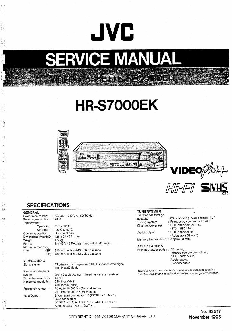
SPECIFICATIONS
GENERAL
Power requirement
Power consumption
Temperature
Operating
Storage
Operating position
Dimensions (WxHxD) :
Weight
Format
Maximum recording
time (SP) :
(LP) :
VlDEO/AU DIO
Signal system
Recording/Playback
system
Signal-toAnmse ratio
Honzontal resolution
Frequency range
Input/Output
: AC 220 - 240 VN, 50/60 HZ
: 28 W
: 5°C to 40"C
: -20°C to 60°C
; Horizontal only
426 x 94 X 341 mm
: 4.5 kg
: SVHSNHS PAL standard with Hi-Fi audio
240 min. with E-240 video cassette
480 min, with E240 Video cassette
: PAL-type colour signal and CCIR monochrome signal,
6251ines/50 iields
: DAA (Double Azimuth) head helical scan system
: 45 dB
: 250 IinesiVHS)
400 lines (s-VHS)
: 70 Hz to 10,000 Hz (Normal audio)
20 Hz to 20,000 Hz (Hi-Fi audio)
: 21-pin scan connector x 2 (lN/OUT xi 1N x1)
RCA connectors
(VIDEO IN x 1, AUDIO IN x 2, AUDIO OUT X l)
S connectors (IN x 1, OUT x 1)
TUNER/TIMER
TV channel storage
capacity
Tuning system
Channel coverage
Aerial output
Memory backup time :
ACCESSORIES
Provided accessories :
: 80 positions (+AUX position "AU")
: Frequency synthesized tuner
: UHF channels 21 - 69
(470 ~ 862 MHZ)
: UHF channel 36
(Adjustable 32 - 4o)
Approx. 3 mini
RF cablei
infrared remote control unit,
"R03" battery x 2,
Audio cable.
S-Video cable
Specifications shown are lo: 5P mode unless orherwrse specified
EA OE, Design and Specifications sub/eel to change Without notice.
COPYRIGHT Q 1995 VICTOR COMPANY OF JAPAN, LTD.
No. 82517
November 1995
Page 2
TABLE OF CONTENTS
Section Title Page
Important Safety Precautions
INSTRUCTIONS
1. DISASSEMBLY
1.1 DISASSEMBLY FLOW CHART ....................................... -
1.2 HOW TO READ THE DISASSEMBLY AND ASSEMBLY -
1.3 DISASSEMBLY/ASSEMBLY METHOD ..
1.4 CASSETTE HOUSING INSTALLATION
1.5 SERVICE POSITION ..........................
1.5.1 How to take out the Mechanism and Main board assemblies .
1.5.2 Cautions on cassette loading when mechanism is in
service position ...........
1.5.3 Cassette loading and ejecting procedures when
mechanism is in service position ................................... 1-5
1.5.4 Opening on the chassis ..... . 1-6
1.6 MECHANISM SERVICE MODE . 1-7
1.6.1 How to set the MECHANISM SERVICE MODE" -7
1.7 EMERGENCY DISPLAY FUNCTION -8
1.7.1 How to display record of an emergency u s -8
1.7.2 Detail of emergency faults ..... . 1-8
1.7.3 How to clear emergency record . . 1-8
2. MECHANISM ADJUSTMENT
2.1 PREPARATION . 2-1
2.1.1 Precautions .
2.1.2 Check without cassette housing assy
2.1.3 Manual removal of loaded tape .
2.1.4 Test Equipment ..............
2.2 MAIN MECHANISM PARTS
2.2.1 Cleaning
2.2.2 Lubrication
2.3 INSPECTION AN .
2.3.1 Suggested servicxng schedule for main odmponen
2.4 DISASSEMBLY/ASSEMBLY PROCEDURE OF MECHANISM
2.4.1 Precaution before disassembling mechanism .
2.4.2 How to set the exclusive mechanism operation mode
(MECHANISM ASSEMBLING MODE)
25 MAIN PARTS REPLACEMENT OF MECHANISM
2.5.1 Pinch Roller Arm Assy
25.2 NC Head ,
2.5.3 Pinch plate
2.5.4 Loading Mote
2.5.5 Lever Assy,Sub Deck Assy,Capstan Motor .
2.5.6 Control Bracket-1,Eanh Plate
2.5.7 Reel Bracket, Slit Disk (take-up)
2.5.8 Control Bracket-2,00ntrol Plate .
2.5.9 Sub Brake (take-up),Control Cam , .2-8
2.5.10 Slide Plate
2.5.11 Change Lever,Rotary Encoder .
2.5.12 Sub Brake (supply), Tension Band Assy,Tension Arm
Assy. Take-up Lever Assy, Slit Disk (supply)
2513 Take -up Head, Tension Ann Lever
2.5.14 Guide Rail ..
2.5.15 Stator Assy.
2.5.16 Rotor Assy
2.5.17 Upper Drum Assy
2.6 CHECKUP AND ADJUSTMENT OF MECHANISM PHASE
2.6.1 Precaution ...............................................................
2.6.2 Loading Arm Assy(supply,take-up) ..............
2.6.3 Rotary Encoder,Change Lever.Control Cam
2.6.4 Slide plate .
2.6.5 Control Plate
2.7 TAPE INTERCHANGEABILITY ADJUSTMENT
2.7.1 Tape pattern ....................
2.7.2 A/C head height & azimuth .
2.7.3 A/C head phase (X-value
2.7.4 LP mode auto tracking
2.7.5 Tension pole position ..
Section Title
3.ELECTRICAL ADJUSTMENT
3.1 PRECAUTION ...................
3.1.1 Required test equipment
3.1.2 Required adjustment tools
.1
3.
.3 Colour bar signaI,colour bar pattern
2 SWITCHING REGULATOR CIRCUIT .
3.2.1 5V DC out put voltage
3.3 SERVO CIRCUIT
3.3.1 PB switching point
3.3.2 Slow tracking preset
3.4 VIDEO CIRCUIT ..
3.4.1 AGC Y LEVEL .
3.4.2 WHITE / DARK CLIP(S-VHSNHS) .
3.4.3 SUB EMPHASIS INPUT LEVEL
3.4.4 PB Y LEVEL (S-VHSNHS)
3.4.5 SP/LP REC COLOUR LEVEL
3.4.6 S-VHS VIDEO EQ ..
3.4.7 PILOT BURST LEV
3.5 SYSCON CIRCUIT
3.5.1 TIMER CLOCK
3.6 AUDIO CIRCUIT ..
3.6.1 AUDIO REC FM
3.7 TUNER CIRCUIT.
3.7.1 RF VCO ........
3.8 Y/C SEP CIRCUIT
3.8.1 DIGITAL IIO LEVEL
4. CHARTS AND DIAGRAMS
SCHEMATIC DIAGRAM NOTES .
CIRCUIT BOARD NOTES ........
4.1 BOARD INTERCONNECTIONS
4.2 SYSCONISERVO BLOCK DIAGRAM .
4.3 AUDIO BLOCK DIAGRAM .
4.4 VIDEO BLOCK DIAGRAM .
4.5 SWITCHING REGULATOR
4.6 SWITCHING REGULATOR CIRCUIT BOARD
4.7 AUDIO SCHEMATIO DIAGRAM
4.8 VIDEO SCHEMATIC DIAGRAM
4.9 SERVO SCHEMATIC DIAGRAM .
4.10 SYSTEM CONTROL SCHEMATI
4.11 VIDEO CPU SCHEMATIC DIAGRAM
4.12 TUNER SCHEMATIC DIAGRAM
4.13 MAIN CIRCUIT BOARD ..............
awuwioi'oibiu
umtpmw
éaéu'nr'nx'aL
4.14 VIDEO UNIT SCHEMATIC DIAGRA 4-33
4.15 VIDEO UNIT CIRCUIT BOARD ...... 4-35
4.16 TERMINAL SCHEMATIC DIAGRAM . . 437
4.17 TERMINAL CIRCUIT BOARD ........ . 4-39
4.16 DEMODULATOR SCHEMATIC DIAGRAM 4-41
4.19 DEMODULATOR CIRCUIT BOARD . 443
4.20 DISPLAY/ SW AND SW / JACK SCHEMATIC DIAGRAM . 4-45
4.21 DISPLAY / SW,SW / JACK,REC SAFETY SW,CASSEI'I'E SW.
DIGITAL SUB AND NO HEAD CIRCUIT BOARDS . 4-47
4.22 PRE/REC SCHEMATIC DIAGRAM . 4-49
4.23 PRE/REC CIRCUIT BOARD ....... . 4-51
4.24 Y/C SEPA SCHEMATIC DIAGRAM . 4-53
4.25 Y/C SEPA CIRCUIT BOARD .......... .4-55
4.26 PDC SCHEMATIC DIAGRAM AND CIRCUIT BOARD . 4-57
4.27 REMOTE CONTROL SCHEMATIC DIAGRAM . 4~58
5. PARTS LIST
5.1 PACKING AND ACCESSORY ASSEMBLY
5.2 CABINET AND CHASSIS ASSEMBLY
5.3 MECHANISM ASSEMBLY
5.4 ELECTRICAL PARTS LIST .......
SW.REGULATOR BOARD ASSEMBLY <01 > .
MAIN BOARD ASSEMBLY <03> ...........
VIDEO UNIT BOARD ASSEMBLY <05>
TERMINAL BOARD ASSEMBLY <06> .
A/C HEAD BOARD <12> ................
DEMOD BOARD ASSEMBLY <14>
DISPLAY/SW BOARD ASSEMBLY <28) .
REC SAFETY BOARD ASSEMBLY <32>
CASS SW BOARD ASSEMBLY <33>
SWITCH/JACK BOARD ASSEMBLY <36)
PREIREC BOARD ASSEMBLY <43>
DIGITAL SUB BOARD ASSEMBLY <49> .
PDC BOARD ASSEMBLY <70> ..
Y/C SEPA BOARD ASSEMBLY <
6 TECHNICAL INFORMATION
6.1 SYSCON CIRCUIT ........................................................... 6-1
['94
ens
'Laut.
LLALLSD
Vuuqmmmbm
mmmmmmmmtpqimmmutmwmm
BBB
Page 51
2.6.3 Rotary Encoder,Change Lever,ControI Cam
(1) When reinstalling the rotary encoder,adjust its position
so as to fit the triangle marks each other and push it deep
untill it is locked by the pawls.
(2) When reinstalling the change lever,set it so as to make
its positioning hole correspond to the hole of the main
deck assy.
(3) When re-engaging the control cam,lower the capstan
brake assy while setting it so as to make its positioning
hole correspond to the hole of the main deck assy.
Rotary Encoder
Claw
Align the _.
triangle marks 1'
Holes align
with hole in deck ,
Fig. 2-6-2
Capstan Brake Assy
Turn the Capstan
Brake Assy
counter clockwise
Holes align
with hole in deck
Control Cam
Fig. 2-6-3
2.6.4 Slide Plate
(1) Lower both the main brake assies (supply and take-up)
untill they touch the edge of the main deck assy while
reinstalling the slide plate so as to make the respective
positioning holes of the main brake assies correspond to
the holes on the main deck assy.
Main Brake Assy(SUP)
Main Brake AssyCT U)
Set Main Brake
Assies to
brake of! position
Hole align
with hole in deck
Slide Plate
Fi942-6-4
2.6.5 Control Plate
(1) Reinstall the control plate so as to set the two position-
ing holes of it on the holes on the main deck assy
respectively and to set the positioning hole of the take-
up lever on the hole of the main deck at the same time.
When adjusting the hole position of the take-up lever,use
a pair of tweezers to hold and move it since it is pulled
by a tension spring.
(2) After reinstalling the control piatejix it with the slit
washer,control bracket-1 and >2.
Holes align
with holes in deck Control Plate
j
Hole of Take-up Lever
align with hole in deck
Slit Washer
Fiu. 2-6-5
2-13