Jvc HMDH 3000 Service Manual

This is the 112 pages manual for Jvc HMDH 3000 Service Manual.
Read or download the pdf for free. If you want to contribute, please upload pdfs to audioservicemanuals.wetransfer.com.

Page: 1 / 112
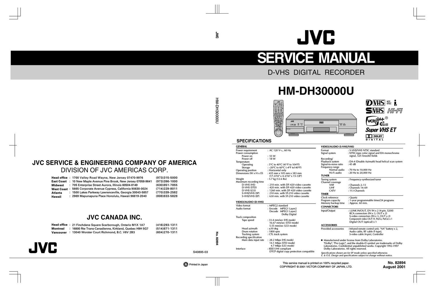
Jvc HMDH 3000 Service Manual

Extracted text from Jvc HMDH 3000 Service Manual (Ocr-read)


Page 1

3N"

ROOOOSHGWH

JVC SERVICE & ENGINEERING COMPANY OF AMERICA
DIVISION OF JVC AMERICAS CORP.

Head office :

East Coast
Midwest

West Coast 1

Atlanta
Hawaii

Head office :

Montreal
Vancouver

1700 Valley Road Wayne, New Jersey 074709976
10 New Maple Avenue Pine Brook, New Jersey 07058-9641

: 705 Enterprise Street Aurora, Illinois 60504-8149

5665 Corporate Avenue Cypress, California 90630-0024
1500 Lakes Parkway Lawrenceville, Georgia 30043-5857

: 2969 Mapunapuna Place Honolulu, Hawaii 96819-2040

JVC CANADA INC.

21 Finchdene Square Scarborough, Ontario M1X 1A7
16800 Rte Trans-Canadienne, Kirkland, Quebec H9H 567
13040 Worster Court Richmond, B.C. V6V 233

(973)315-5000
(973)396-1000
(630)851-7855
(714)229-8011
(770)339»2582
(808)833-5828

(416)293-1311
(514)871-1311
(604)270-1311

V6838 'ON

840895-03

JVC
SERVICE MANUAL

D-VHS DIGITAL RECORDER

HM-DH30000U

mvns - i.

Hi=Fi
W. o

VCRW Gin

Super VHS ET

SPECIFICATIONS

GENERAL VIDEO/AUDIO (S-VHS/VHS)

Power requirement : AC 120 VI», 60 Hz Format : S-VHS/VHS NTSC standard

Power consumption Signal system :NTSC-type color signal and EIA monochrome
Power on : 55 W signal, 525 lines/60 fields
Power off : 18 W Recording/

Temperature Playback system : DA-4 (Double Azimuth) head helical scan system
Operating : 5°C to 40°C (41°F to 104°F) Signal-to-noise ratio :45 dB
Storage : ~20°C to 60°C (43°F t0140°F) Frequency range

Operating position
Dimensions (W x H x D)

Weight

Maximum recording time
D»VHS (HS)
D-VHS (STD)
D-VHS (LS3)
S-VHS/VHS (SP)
S-VHS/VHS (EP)

VIDEO/AU DIO (D-VHS)

: Horizontal only
: 435 mmx 105 mmx383 mm

(17-3/16" x 4-3/16">< 15-1/8")

: 5.7 kg (12.6 lbs)

: 210 min. with DF-420 video cassette
: 420 min. with DF-420 video cassette
: 1260 min. with DF-420 video cassette
: 210 min. with ST-21 0 video cassette
: 630 min. with ST-21 0 video cassette

Video format
Audio format

Track composition
Tape speed

Head azimuth
Drum rotation
Tracking system
Recording specification
Main data input rate

I nte rface

: MPEGZ standard
:Encode

MPEG1 Layer2
Decode MPEG1 Layer2
Dolby Digital

: 33.4 mm/sec (HS mode)

16.67 mm/sec (STD mode)
5.55 mm/sec (LS3 mode)

: :30 deg
: 1800 rpm
: CTL track system

: 28.2 Mbps (HS mode)

14.1 Mbps (STD mode)
4.7 Mbps (LS3 mode)

:IEEE1394 compliant

DTCP digital copy protection compatible

Normal audio
Hi-Fi audio
TUNER

:70 HZ to 10,000 Hz
:20 HZ to 20,000 Hz

Tuning system
Channel coverage
VHF
UHF
CATV
TIMER

: Frequency-synthesized tuner

: Channels 2713
: Channels 14769
: 113 Channels

Clock reference
Program capacity
Memory backup time
CONNECTORS

: Quartz
: 1-year programmable timer/24 programs
: Approx. 60 min.

Input/Output

ACCESSORIES

:i.L|NK lN/OUT, DV IN x 2 (4-pin, 5200)

RCA connectors (IN X 3, OUT X 2)
S-video connectors (IN x 3, OUT x 2)
Component video OUT (Y, Pia/CB, PR/CR) x 1
Digital OUT (optical) >

Provided accessories

: Infrared remote control unit, AA battery x 2,

Audio cable, RF cable (F-type),
S-video cable (4-pin), Controller

I Manufactured under license from Dolby Laboratories.
"Dolby", "Pro Logic", and the double-D symbol are trademarks of Dolby
Laboratories. Confidential unpublished works. Copyright 1992-1997
Dolby Laboratories. All rights reserved.

Specifications shown are for SP mode unless specified otherWise.
E. & ().E. Design and specifications stibiect to change Without notice.

3/ x. y _
$9 Printed in Japan

T

This service manual is printed on 100% recycled paper.
COPYRIGHT © 2001 VICTOR COMPANY OF JAPAN, LTD.

No. 82894
August 2001

Page 2

TABLE OF CONTENTS

Section Title Page
Important Safety Precautions
INSTRUCTIONS

1. DISASSEMBLY
1.1 Disassembly flow chart .........................
1.2 How to read the disassembly and assembly
1.3 Disassembly/assembly method
1.4 Service position
1.4.1 How to set the SerVIce posItIon
1.4.2 Precautions for cassette loading in the Service position"
1. 4. 3 Cassette loading and ejection" methods in the Service position"
1. 5 Mechanism service mode .....
1. 5.1 How to set the Mechanism service mode"
1.6 Jig RCU mode
1.6.1 Setting the Ig mo e .
1. 6. 2 Setting the User RCU mode
1. 7 Opening on the chassis...
1. 8 Emergency displaylunction .....
1. 8.1 Displaying the EMG informatIon
1.8.2 Clearing the EMG history
1.8.3 EMG content description .
1.8.4 EMG detail information <1>
1.8.5 EMG detail information <2>


2. MECHANISM ADJUSTMENT

2.1 Belore starting repair and adjustment
2.1. 1 Precautions ...............
2.1. 2 Checking for proper mechanical operation

2.1. 3 Manually removing the cassette tape
2.1.4 Jigs and tools required for adjustment
2.1. 5 Maintenance and inspection.
2. 2 Replacement of major parts .....
2. 2. 1 Before starting disassembling (Phase matchlng between
mechanical parts) ......
2.2.2 How to set the Mechanism assembling mode"
2.2.3 Cassette holder assembly
2.2.4 Pinch roller arm assembly
2.2.5 Guide arm assembly and press lever assembly
2.2.6 A/C head .....
2.2.7 Loading motor .
2.2.8 Capstan motor
2.2.9 Pole base assembly (supply or take-up s e)
2.2.10 Rotary encoder
2.2.11 Clutch unit .....
2.2.12 Change lever assembly, direct gear, clutch gear and coupling gear.. 2-10
2.2.13 Link lever ..........
2.2.14 Cassette gear, control cam and worm gear
2.2.15 Control plate ............
2.2.16 Loading arm gear (supply or take-up side) and
loading arm gear shaft ...................
2.2.17 Take-up lever, take-up head and control plate guIde
2.2.18 Capstan brake assembly.
2.2.19 Sub brake assembly (take- up side)...
2.2.20 Main brake assembly (take up side) reel disk (take up sIde) and
main brake assembly (supply side)...
2.2.21 Tension brake assembly, reel disk (supply side) and
tension arm assembly ..........
2.2.22 Idler lever, idler arm assembly
2.2.23 Stator assembly .......
2.2.24 Rotor assembly .......
2.2.25 Upper drum assembly
2.3 Compatibility adjustment
2.3.1 FM waveform linearity
2.3.2 Height and tilt ol the A/
2.3.3 A/C head phase (X-value)
2.3.4 Standard tracking preset .
2.3.5 Tension pole position .......................


ea

3. ELECTRICAL ADJUSTMENT
3.1 Precaution ............
3.1.1 Required test equipments .
3.1.2 Required adjustment tools .
3.1.3 Color (colour) bar signal,Color (colour) bar pattern 3-1
3.1.4 Switch settings and standard precautions
3.1.5 EVR Adjustment.
3.2 Servo circuit
3.2.1 Switching p nt
3.2.2 D-VHS switching point .
3.2.3 Slow tracking preset ..

Section Title Page

3.3 Video circuit
3.3.1 D/A level ..
3.3.2 EEY/PBY (S-VHS/VHS) level .
3.3.3 REC color (colour) level
3.3.4 Video EQ (Frequency response).
3.3.5 Auto picture initial setting

3.4 Audio circuit ......
3.4.1 Audio REC FM

3.5 Demodulator circu
3.5.1 Input level
3.5.2 Stereo VCO
3.5.3 Stereo filter.
3.5.4 Separation - 1
3.5.5 Separation - 2
3.5.6 SAP VCO

3.6 Digital circuit ..
3.6.1 D-VHS REC level .
3.6.2 PLL f0 ............

4. CHARTS AND DIAGRAMS
NOTES OF SCHEMATIC DIAGRAM
CIRCUIT BOARD NOTES ..........
4.1 BOARD INTERCONNECTIONS
4.2 REGULATOR AND SUB REGULATOR SCHEMATIC DIAGRAMS . .4-5
4.3 MAIN (VIDEO/AUDIO) SCHEMATIC DIAGRAM
4.4 MAIN (SYSCON) SCHEMATIC DIAGRAM
4.5 MAIN (TUNER/DEMOD) SCHEMATIC DIAGRAM
4.6 MAIN (AUDIO l/O) SCHEMATIC DIAGRAM ..
4.7 MAIN (SYNCDET) SCHEMATIC DIAGRAM
4.8 MAIN (MAIN- TERMINAL) SCHEMATIC DIAGRAM.
4. 9 3D DIGITAL/4M SCHEMATIC DIAGRAM.
4.10 TERMINAL- NTSC SCHEMATIC DIAGRAM.
4.11 S-SUB SCHEMATIC DIAGRAM
4.12 DISPLAY, REC SAFETY/D.CASS SW AND
JACK SCHEMATIC DIAGRAMS .....
4.13 D-PRE/REC SCHEMATIC DIAGRAM
4.14 DIGITAL(HOST) SCHEMATIC DIAGRAM.
4.15 DIGITAL(DMA|N) SCHEMATIC DIAGRAM ..
4.16 DIGITAL(D-VHS IF) SCHEMATIC DIAGRAM
4.17 DIGITAL(DVX) SCHEMATIC DIAGRAM
4.18 DIGITAL(VIDEO IF) SCHEMATIC DIAGRAM
4.19 DIGITAL(HD DEC) SCHEMATIC DIAGRAM
4.20 DIGITAL(LAPRAS) SCHEMATIC DIAGRAM
4.21 DIGITAL(DSP) SCHEMATIC DIAGRAM
4.22 DIGITAL(AUDIO AD/DA) SCHEMATIC DIAGRAM.
4.23 DIGITAL(DECRIPTER) SCHEMATIC DIAGRAM
4.24 REGULATOR AND SUB REGULATOR CIRCUIT BOARDS
4.25 3D DIGITAL/4M AND S-SUB CIRCUIT BOARDS
4.26 TERMINAL CIRCUIT BOARD .........................
4.27 DISPLAY, REC SAFETY AND JACK CIRCUIT BOARDS
4.28 D-PRE/REC CIRCUIT BOARD ..............
4.29 DIGITAL CIRCUIT BOARD
4.30 MAIN CIRCUIT BOARD
4.31 VOLTAGE CHARTS.....
4.32 FDP GRID ASSIGNMENT AND ANODE CONNECTION
4.33 REMOTE CONTROLLER SCHEMATIC DIAGRAM
4.34 WAVEFORMS
4.35 CPU PIN FUNCTION
4.36 SYSTEM CONTROL BLOCK DIAGRAM
4.37 AUDIO BLOCK DIAGRAM .
4.38 VIDEO BLOCK DIAGRAM .
4.39 D-VHS BLOCK DIAGRAM .

5. PARTS LIST

5.1 PACKING AND ACCESSORY ASSEMBLY

5.2 FINAL ASSEMBLY ..........

5.3 MECHANISM ASSEMBLY

5.4 ELECTRICAL PARTS LIST .....
SW.REG BOARD ASSEMBLY <01>
SUB REG BOARD ASSEMBLY <02>
MAIN BOARD ASSEMBLY <03>
3D DIGITAL/4M BOARD ASSEMBLY <05> .
TERMINAL BOARD ASSEMBLY <06>
A/C HEAD BOARD ASSEMBLY <12>
S-SUB BOARD ASSEMBLY <15> .
DISPLAY BOARD ASSEMBLY <28>
REC SAFETY BOARD ASSEMBLY <32>
JACK BOARD ASSEMBLY <36>
D-PRE/REC BOARD ASSEMBLY <43>
DIGITAL BOARD ASSEMBLY <50>
LOADING MOTOR BOARD ASSEMBLY <55> ...................