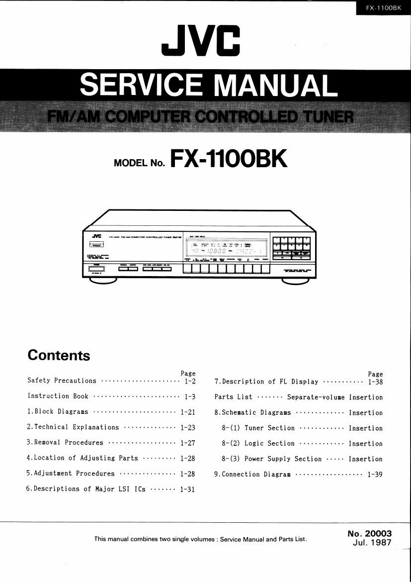
Jvc FX 1100 BK Service Manual
This is the 62 pages manual for Jvc FX 1100 BK Service Manual.
Read or download the pdf for free. If you want to contribute, please upload pdfs to audioservicemanuals.wetransfer.com.
Extracted text from Jvc FX 1100 BK Service Manual (Ocr-read)
Page 1
FX~11008K
SERVICE MANUAL
MODEL No. FX-11OOBK
.M: w.m~,~mme_ --- ,
El 5 l . .
=a'i-=: ._.,. ____.._..., :'__ -
$5.5m lllllllll W
\~__J' \~_-)
Contents
Page Page
Safety Precautions --------------------- 1-2 7.Description of FL Display ----------- 1-38
Instruction Book ----------------------- 1-3 Parts List ------- Separate-volume Insertion
1.Block Diagrams ---------------------- 1-21 8.Schematic Diagrams ------------- Insertion
2.Technical Explanations -------------- 123 8-(1) Tuner Section ------------ Insertion
3.Removal Procedures ------------------ 1-27 8-(2) Logic Section ------------ Insertion
4.Location of Adjusting Parts --------- 1'28 8-(3) Power Supply Section ----- Insertion
5.Adjustment Procedures --------------- 1-28 9.Connection Diagram ------------------ 1-39
6.Descriptions of Major LSI ICs ------- 1-31
No.20003
This manual combines two single volumes: Service Manual and Parts List. Jul 1987
Page 2
FX-11003K
Safety Precautions
1. The design of this product contains special hardware and
many circuits and components specially for safety pur-
poses.
For continued protection, no changes should be made to
the original design unless authorized in writing by the
manufacturer. Replacement parts must be identical to
those used in the original circuits. Service should be
performed by qualified personnel only.
2. Alterations of the design or circuitry of the product
should not be made. Any design alterations or additions
will void the manufacturer's warranty and will further
relieve the manufacturer of responsibility for personal
injury or property damage resulting therefrom.
3. Many electrical and mechanical parts in the product
have special safetyarelated characteristics. These charac-
teristics are often not evident from visual inspection nor
can the protection afforded by them necessarily be ob-
tained by using replacement components rated for higher
voltage. wattage, etc, Replacement parts which have
these special safety characteristics are identified in the
Parts List of Service Manual. Electrical components
having such features are identified by shading on the
schematics and by ( A )on the Parts List in the Service
Manual. The use of a substitute replacement which does
not have the same safety characteristics as the recom-
mended replacement part shown in the Parts List of
Service Manual may create shock, fire, or other hazards.
4. The leads in the products are routed and dressed with
ties, clamps, tubings, barriers and the like to be sepa-
rated from live parts, high temperature parts, moving
parts and/or sharp edges for the prevention of electric
shock and fire hazard.
When service is required, the original lead routing and
dress should be observed, and it should be confirmed
the they have been returned to normal, after re-assembl-
Ing.
fl
5. Leakage current check
(Electrical shock hazard testing)
After re-assembling the product, always perform an
isolation check on the exposed metal parts of the
product (antenna terminals, knobs, metal cabinet,
screw heads, headphone jack, control shafts, etc.) to be
sure the product is safe to operate without danger of
electrical shock.
Do not use a line isolation transformer during this check.
' Plug the AC line cord directly into the AC outlet.
Using a Leakage Current Tester, measure the
leakage current from each exposed metal part of the
cabinet, particularly any exposed metal part having a
return path to the chassis, to a known good earth
ground. Any leakage current must not exceed 0.5 mA
AC ir.m.s.).
0 Alternate check method.
Plug the AC line cord directly into the AC outlet. Use
an AC voltmeter having 1,000 ohms per volt or more
sensitivity in the following manner. Connect a 1.500 I)
10 W resistor paralleled by a 0.15 F AC-type
capacitor between an exposed metal part and a known
good earth ground.
Measure the AC voltage across the resistor with the
AC voltmeter.
Move the resistor connection to each exposed metal
part, particularly any exposed metal part having a
return path to the chassis, and measure the AC
voltage across the resistor. Now, reverse the plug in
the AC outlet and repeat each measurement. Any
voltage measured must not exceed 0.75 V AC ir.m.s.).
This corresponds to 0.5 mA ACir.m.s.).
AC VOLTMETER
m (HAVING 1000 n/v,
OR MORE SENSITIVITY)
C
0.15 uF AC-TYPE
150011 10W
GOOD EARTH GROUND
PLACE THIS PROBE
ON EACH EXPOSED
METAL PAFlT.
Fig. 1
this equipment.
CAUTION :
CHECK THE VOLTAGE SELECTDR S SETTING
(Except for the U.S.A., Canada, Australia, the U.l(. and Continental Europe)
Before inserting the power plug. please check that the voltage selectors setting corresponds with
the line voltage in your area. If it doesn't he sure to reset the voltage selector before operating
The voltage selector may be located on the rear or bottom of the unit, or underneath the platter.
Before setting the voltage selector to the proper voltage, disconnect the power plug.
1-2 (No. 20003)
Page 21
6
. To release the Preset Scanning operation
midway, press the PRESET UP (or PRESET
DOWN) button again.
The Preset Scanning operation stops and the
preset channel which is being received at
that time will continue to be received.
Recording broadcasts
l,
2.
5.
How to record broadcasts
Press the POWER button to turn the power
on.
Tune to the broadcast to be recorded. For
details, refer to Listening to broadcasts" on
page 27.
. Press the REC CAL button and adjust the
recording level control of the tape deck
so that the recording level meter indicates
D VU
. After recording level adiustmentiscomplete,
press the REC CAL button so that the REC
CAL signal is no longer output.
Set the tape deck for recording. For more
details, refer its instruction book.
How to perform unattended remrd'ng
As this unit does not have a built-in timer,
3
o
1.
separate timer is necessary.
Unattended recording of one broadcast
If the PROGRAM indicator is not lit and
power is applied again, the last frequency re-
ceived before power was switched off will be
received and recorded automatically. Make
sure to tune the desired station before switch-
ing the tuner off.
Programmed recording
The programming tunction of this unit
permits up to 8 broadcasts, either AM or
FM, to be programmed for unattended re»
cording,
First connect the power cord to the timer
and program the broadcasts, then set the
timer according to the desired time and
set thetepe deck for recording.
Press the PROGRAM button so that the
PROGRAM indicator lights, and set the
deck to the recording mode.
Leave the power switches of all components
ON, and set the timer to the standby mode.
. When the preset on time is reached, power
will be squlied to each component, and the
first programmed station (PRGM-i) will be
received by the tuner.
In this way, whenever power is supplied to
the tuner at preset ON times, the received
station will automatically change in the
programmed order to record them.
I How to program broadcasts
1.
First decide the order in which the broad-
casts are to be arranged in the program, then
press the MONITOR button.
. The "PROGRAM" and "MONITOR" indi-
cators light simultaneously. And at the
same time, "PGM-1.. is displayed in the
character display section, while the preset
channel number or -v" blinks in the PRE-
SET CHANNEL display.
6
. Zur Abschaltung der Anspielfunktion die
PR ESET UP- oder DOWN»Taste betatigen.
Die Anspielfunktion wird abgebrochen und
die zu diesem Zeitpunkt empfangene Fre-
quenz wird beibehalten.
Aufnahme von Radiosendungen
l Bedionxchrino
1.
2.
. Das
Das Geréit mit der POWER~Taste einschalten.
Den fiir die Aufnahme vorgesehenen Sender
einstellen. Weitere Angaben hierzu siehe
Abschnitt "Empfang yon Radiosendungen"
auf Seite 27.
. Die REC CALATaste betatigen und den
Aufnahmepegel des Magnetaufzeichnungs-
gerats so aussteuern, dais die VU-Meter-
Anzeige Del 0 VU Iiegt.
. Nach dieser Aussteuerung erneut die REC
CALrTeste betfitigen, um die Eichsignalab-
gabe zu beenden.
Magnetaufzeichnungsgerat aut Aut-
nahme schaiten. Angaben hierzu sienedessen
Bedienungsanleitung.
I Uniibarwachte Aufnahman
Da dieses Gera't keine eingebaute Schaltuhr
besitzt, ist eine externe Schaltuhreinheit erfor-
derlich.
e Uniiborwachte Aufnahme eines Senders
Bei erneutem Einschalten des Gerats, ohne
leuchtende PROGRAM-Anzeige, wird die
jeweils zuletzt empfangene Frequenz einv
gestellt und automatisch aufgenommen.
Siohergehen, dais bei Abschalten des Tuners
der gewiinschte Sender eingestellt ist.
o Programmiano Aufnah me
it
Diese Funktion erlaubt die uniiberwachte
programmierte Aufnahme you his zu 8 Sen-
dungen (UKW oder MW).
Zunachst das Netzkabel an der Schaltuhr
anbringen und die Sender eingeben. Hierauf
die vorgesehene Zeit an der Schaltuhr ein-
stellen und das Magnetautzeichungsger'at auf
Aufnahme schaiten.
Die PROGRAM-taste betatigen, so def; die
PROGRAM-Anzeige leuchtet. Den Recorder
auf Aufnahme schalten.
. Bei allen Komponenten die Spannungsver-
sorgung eingeschaltet lassen und die
Schaltuhr auf Betriebsbereitschaft stellen
. Bei Erreichen der vorbestimmten Einr
schaltzeit erfolgt Spannungsversorgung fiir
alle angeschlossenen Komponenten und der
erste vorbestimmte Sender iFRGM-i) wird
empfangen.
. Bei ieder weiteren schaltuhrgesteuerten
Einschaltung wird jeweils der vorbestimmte
Sender empiangen (in Eingabereihenfolgelt
I Programminnn von Sendern
l.
Zunachst die Reihenfolge der zu empfengen-
den Sender festlegen. Dann die MONITOR-
Taste betatigen.
. PROGRAM- und MONITOR-Anzeige leuchr
ten. G leichzeitig erscheint AnIeige "PRGM-i
im alphanumerischen Display und die
Senderspeichernummer oder "- - blinkt im
PRESET CHANNEL-Display.
6
E
I
1 .
2.
I
C
. Enfoncer
FX-11003K
. Pour relacher le balayage des prereglages en
cours, appuyer a nouveau sur la touche
PRESET UP (ou PRESET DOWN).
Le balayage des préréglages s'arrete et le
canal préréglé qui est recu a ce moment
continuera a etre recu.
nreg'stlement démissions
Comment procéder
Enfoncer Iinterrupteur POWER pour four-
nir I'aiimentation.
Syntoniser sur l'émission a enregistrer. Pour
plus de détaiis, se référer a Ecoute d'érnis»
sions", page 27.
Ie commutateur REC CAL et
régler Ie niveau d'enregistrement avec la
commando de la platine pour que le comp-
teur de niveau denregistrement indique
D VU
. Apres réglage du niveau d'enregistrement,
appuyer sur la touche REC CAL pour
arréter la sortie du signal REC CAL.
. Regler la platine pour l'enregistrernent, Pour
plus de détails, consulter son manuel d'ins-
tructions.
Enragistrement diftéri
et appareii no comportant pas de minuterie
incorporee, une minuterie separée est neces-
saire,
1.
I
1.
, Les indicateu rs
Enregstmnent ditfévé d'unc amission
Si l'indicateur PROGRAM n'est pas allurne et
que l'alimenmtion est fournie é nouveau, la
lréquence recue avant que celleci soit coupée
sera recue et enregistrée automatiquement.
Sassurer de syntoniser Ia station voulue avant
de mettre le syntoniseur hors tension.
Enragistrement prowamm
La programmation est possible sur 8 emis-
sions, soit AM, soit FM pour lenregistre-
merit difféé.
Raccorder d'abord le cordon d 'alimentation
a la minuterie et programmer les emissions
puis regler la minuterie selon l'heure désirée
et régler la platine pour I'enreigstrement.
. Appuyer sur la touche PROGRAM pour que
lindicateur PROGRAM sallume, et régler la
platine en mode d'enregistrement.
Laisser les interrupteurs d'alimentation de
tous les appareils sur ON, et régler la
minuterie en mode d'attente.
. Ouand l'heurede mise en marche arrive, Iali»
mentation est fournie a tous les appareils, et
la premiere station préréglée iPRGM-ll sera
recue par le syntoniseur.
. De cette facon, quand l'alimentation est
fournie au syntoniseur a cheque mise en
marche, la station recue changera auto-
matiquement dans l'ordre pregrammé pour
Ienregistrer.
Comment programmer dos emissions
D'abord decider l'ordre dans lequel les
émissions vont etre arrangées dans Ie pro
gramme, puis appuyer sur la touche MONI-
TOR.
PROGRAM" et "MONI-
TOR" sallument simultanément, Et en
mame temps, PRGM-l " est ei'fiché dans la
partie daflichage de caractere, tandis que
le numero de canal preregléou "- A" clignote
dans I'affichage PR ESET CHAMNEL.
(No. 20003) 1-1 7