Jvc DXE 10 BK Service Manual

This is the 17 pages manual for Jvc DXE 10 BK Service Manual.
Read or download the pdf for free. If you want to contribute, please upload pdfs to audioservicemanuals.wetransfer.com.

Page: 1 / 17
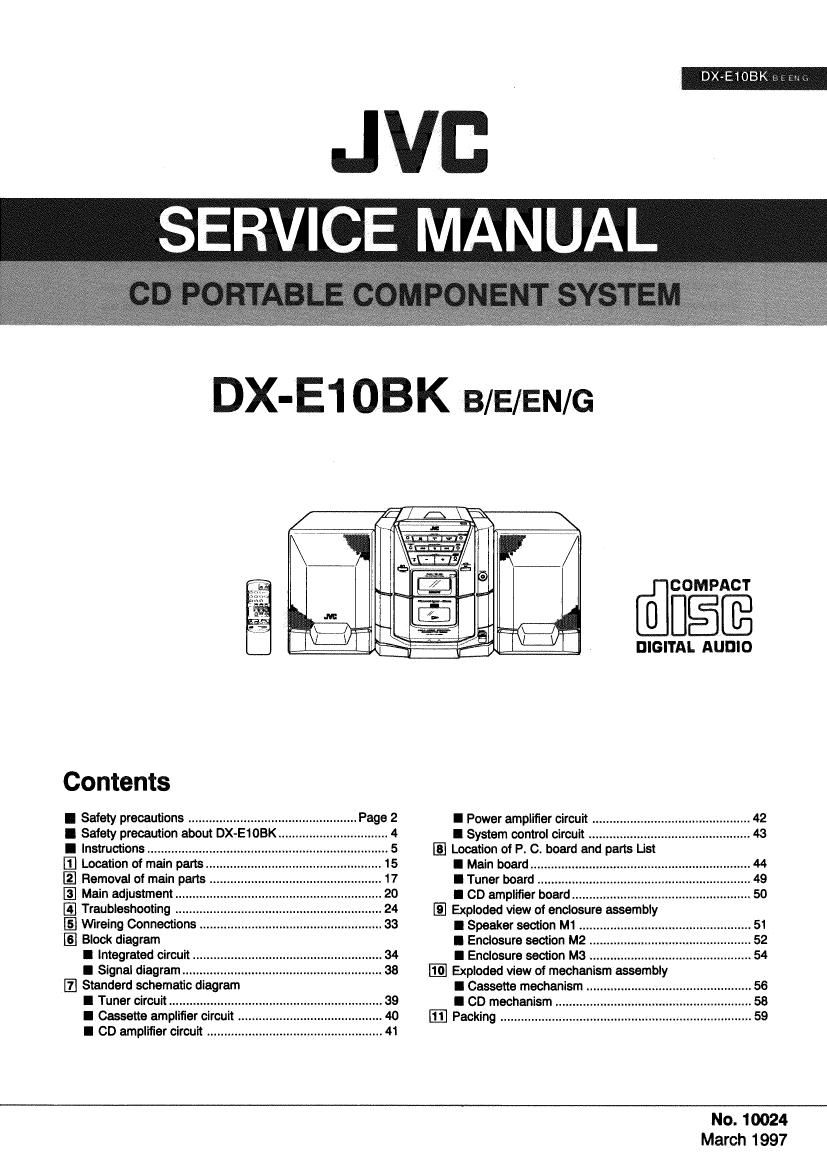
Jvc DXE 10 BK Service Manual

Extracted text from Jvc DXE 10 BK Service Manual (Ocr-read)


Page 1

DX-E1OBK , mt

.JVD
SERV'CE MANUAL

DX-E1OBK B/E/EN/G

Contents

I Safety precautions ......................
I Safety precaution about DX-E1 OB
I Instructions ...................
El Location of main parts.
Ea] Removal of main parts .
E] Main adjustment
[.3 Traubleshooting
E] Mreing Connections
Block diagram
I Integrated circuit ..
l Signal diagram .....
[Z] Standard schematic diagram
I Tuner circuit ....................
I Cassette amplifier circuit ..
I CD amplifier circuit ................................................... 41

(dig?

DIGITAL AUDIO

I Power amplifier circuit ..

I System control circuit
Location of P. C. board and parts List
I Main board ..

I Tuner board

I CD amplifier boar .
Exploded view of enclosure assembly
I Speaker section M1 ......

I Enclosure section M2

I Enclosure section M3
Exploded view of mechanism assembly
I Cassette mechanism .

I CD mechanism ..

Ifi] Packing

No. 10024
March 1997

Page 2

DX-E1 65K mm

32

I Description of Error Display/Indication

in addition to the normal functions, the service test modes have been incorporated in this model for confirmation and
adjustment as described below:

1. Settlng oftheSeWiceTest Mode

6 Setting Method
After the power supply has been turned on, it is possible to set this model to the service test mode from the normal
function conditions:

When the three -, PLAY MODE and STOP buttons on the are pressed at the same time, this model

will be set to the test mode. When this model has been set to the test mode, all of the LCDs will be turned on.

0 Release of setting
When this model has been set to the test mode, press the three POWER , PLAY MODE and STOP buttons

at the same time, set this model to the backup mode or reset this model. Then, the test mode will be released.

2. Self- Diagnosis Function of CD Servo
When any error has occurred, either of the following error codes will be displayed depending on the contents of the error:
1) Err 1: Failure to turn on the reset switch (Internal peripheral feeding time-out)
2) Err 2: Failure to turn aft the reset switch (Outerperipheral feeding time- out)
3) Err 3: Focusing failure
4) Err 4: TOC reading failure
5) Err 5: Failure to read the 0 code continuously for 3 seconds
6) Err 6: Failure to locate thebeglnnlng of music when selecting a music
7) Err7: Spindle servo failure