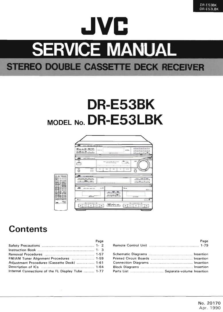
Jvc DRE 53 LBK Service Manual
This is the 115 pages manual for Jvc DRE 53 LBK Service Manual.
Read or download the pdf for free. If you want to contribute, please upload pdfs to audioservicemanuals.wetransfer.com.
Extracted text from Jvc DRE 53 LBK Service Manual (Ocr-read)
Page 1
DR7E53BK
DR-E53LBK
.JVI:
SERVICE MANUAL
DR-E53BK
MODEL No. DR-E53LBK
Contents
Page Page
Safety Precautions t I- 2 Remote Control Unit .......................................... 1-79
Instruction Book ....... . 1» 3
Removal Procedures . 1»57 Schematic Diagrams ., .. Insertion
FM/AM Tuner Alignment Procedures . 1-59 Printed Circuit Boards Insertion
Adjustment Procedures (Cassette Deck) . 1-61 Connection Diagrams .. Insertion
Description of ICS . 1-64 Block Diagrams . ......................... Insertion
Internal Connections of the FL Display Tube . t 1-77 Parts List .......... , Separate-volume Insertion
No. 20170
Apr. 1990
Page 2
1
DR E 535K
DR~E53LBK
1. The design of this product contains special hardware and many Circuits and components specially tor safety purposes.
For continued protection, no changes should be made to the original design unless authorized in writing by the
manufacturer. Replacement parts must be identical to those used in the original circurts. Service should be per-
formed by qualified personnel only.
2. Alterations of the design or circuitry of the product should not be made. Any design alterations of the product
should not be made. Any design alterations or additions vvill void the manufacturer's warranty and will further
relieve the manufacturer of responsibility for personal injury or property damage resulting therelrom.
3. Many electrical and mechanical parts in the product have special safety-related characteristics. These characteristics
are often not evident from visual inspection nor can the protection afforded by them necessarily be obtained by
using replacement components rated for higher voltage, wattage, etc. Replacement parts which have these special
safetv characterislics are identified in the Parts List of Service Manual. Electrical components having such features
are identified ltv shading on the schematics and by (_'. l on the Parts List in the Servme Manual. The use of a sub-
stitute replacement which does not have the same safety characteristics as the recommended replacement part shown
in the Parts List nl Service Manual may create shock, fire, or other hazards.
4. The leads in the products are routed and dressed with ties, clamps, tunings, barriers and the like to be separated from
live parts, high temperature parts, moving parts antlfor sharp edges for the prevention of electric shock and fire hazard.
When service ét required, the original lead routing and dress should be obseived, and it should be confirmed that they
have been returned to nmmal, alter re-assembling.
5. Leakage current check (Electrical shock hazard testing)
Alter re-astembling the product, always perform an isolation check on the exposed metal parts o! the product
(antenna terminals, knobs, metal cabinet, screw heads, headphone jack, control shafts, etc.) to be sure the product
is safe to operate without danger of electrical shock.
Do not use a line isolation transformer during this check.
I Plug the AC line cord directly into the AC outlet. USHlg a "Leakage Current Tester", measure the leakage current
lrorri each exposed metal part of the cabinet, particularly any exposed metal part having a return path to the
chasm, to a known good earth ground. Any leakage current must not exceed 0.5 mA AC lr ms).
0 Alternate check method
Plug the AC line cord directly into the AC outlet. Use an AC voltmeter having 1,000 ohms per volt or more sensi
tivity in the tollowrng manner. Connect a 1,500 9 10 W resistor paralleled by a 0.15HF ACAtype capacitor be
tween an exposed metal part and a known good earth ground.
Measure the AC voltage across the resistor with the
AC voltmeter.
Move the resistor connection to each exposed metal
{Safety Precautions
l
AC VOLTMETER
(Hat/trig 1000 ohms/volt.
or more senlrtmty l
part, particularly any exposed metal part having a " LJ 7
return path to the chassis, and measure the AC volt ° J C 6
age across the resistor. Now, reverse the plug in the k mace 5 probe
AC outlet and repeat each measurement. Any voltage ,_t_i._mn.. -z- on each exposed
measured must not exceed 0.75 VAC (r.m.s.). This isoon ~ow metal part-
corresponds to 0.5 mA AC (r.m.s.). "
Good earth around
rWarning , -
. This equipment has been designed and manufactured to meet international safely standards.
It is the legal responsibility of the repairer to ensure that these safety standards are maintained.
Repairs must be made in accordance with the relevant safety standards.
It is essential that safety critical components are replaced by approved parts.
If mains voltage selector is provided, check setting for local voltage.
999N
2 lNo. 20170)
Page 24
DR-E53BK
DP E53LBK
rerun
Ell-:1
Note:
- Vou cannot program statlons whlle the
MEMORY indicator Is all. when the
MEMORY Indicator Is oft. press the
MEMORY button agaln.
Auto memory programming
L. . » .
Notes:
0 It a new station is programmed in a
preset stations button In which another
has already been programmed. It will
override the existing station preset.
- Statlon presets could be cancelled if the
power plug IS disconnected trom the out-
let or power is interrupted. In this case,
preset the stations agaln,
'When you want to stop auto memory,
press TUNING (up or down) button.
Listening to another source connected with
this equlpment.
PHONO, CD, DAT or VCR
- tel
. "amt (t
l 24 (No. 201/0}y
(vb at? -
l
b
Achtung:
Sender kénnen nur progmmmien werden.
wenn die MEMORY-Anzelge autleuchtet.
Bleibt die Anzelge ounkel, emeut clle
MEMORY-Taste drl'icken.
Automatlsches Speichem von Programm-
pla'tzen
, v.2 ,. .: w . u'lZ . .lx
Achtung:
- erd ein Sender aut einem bereits beleg-
ten Programmplatz gespelchen, so wlrd
der dort gespeicherte Sender geldscht.
- Bel Trennung des Gerfites vom Netz oder
bel Stromaustall kb'nnten gespelcherte
Programmpléitze geléscht warden. ln ei-
nem solchen Fall sind die Sender emeut
zu programmieren.
°Zum Abbruch des automatlschen Spel-
cherbetriebs clle lUNlNG-Taste (aut Oder
ab) driicken.
Anhoren elner anderen angeschlossenen
Tanquelle.
PHONO. CD, DAT odor VCR
mmjw- -.
Hemarque:
- La programmatlon des présélectlons est
Impossible si la témoln MEMORY n'est pas
allume. S'il seteint, pressez MEMOFW i
nOUVEBUV
Programmation automémorisee
7, ,uft m l,.v
-w,.t
raj: .w
Hemarques:
. Toute nouvelle programmation d'un
emeneur sous un numéro ou ll y en avait
un autre, supplante le premier.
- La programmation des présé|ectlons
peut disparaitre si lon retire Ia tiche see
teur de la prise de courant ou 5' y a une
coupure de caurant. Dans ce cas, i| taut
reprogrammer.
- Lorsqu'on veut arréter Ia mémolre auto-
mathue, entoncer Ia bouton de synta-
nlsatlon (TUNING) (vers le haut ou vers
Ie has).
Ecoute d'une autre source rellée a cet
appareil.
PHDNO, CD, DAT ou VCR
. . was» set now 5
Page 48
DFi-ESBBK
DR-E53LBK
1-48
TUNER: V g in PM 4'
the timer 7 ,
TUNER TIMER REQ: :LL '7' ; "HM the
TUNER by wrlug 'he l'vzei
:r r / setting
CD: "iglu'g L7: LN v lg l'u. ' u-
PHONO: 9m use rds by sci: 'uier
TAPE: Play rig laws by setting 1»; {um}!
I Setting the timer
TUNER: 51-2-2 a, 1": 0
CD: Sr 30? and mm Ui r- Ci niafi' 2
PHONO 'u i 'r .: .if my:
ther Milli 9'»! '"a w 3
TAPE:
"2 ; JDs i- «filly! mu , L m! .2
{minimum L w , «Vi
i..." w. ' « Anla-
11:, 3 Mun-i: in Mr v with D lwi
Notes:
- To reset the tlmerI press the CANCEL
button.
. Do not use the remote control until dur~
Ing setting at the timer to avoid errors in
opemtlon.
- It the TUNER is used while the timer is on,
specified times are canceled.
caution lor using timer
Setting ml the timer, while holding the CSRP
"ON, may cause unexpected large volume
when the power is activated by the timer. To
prevent this, previausly set the same source
which is preset with the timer, or set the
CSRP to OFF.
(No. 20170)
TUNER: LI
will -i i: yea 'i
TUNER Tim REC]: Aulr-ain»; vom RADIO
mi: Hillt ' n
L veines FM- Oder AM- Senders
"JAYS
CD' E @CDN
: nun" 2
e L»; . Plan»,
:- 'Huqofl
an i we 5
Achtung:
- Den Timer durch Beth'tlgung der CANCEL
- Zur Venneldung Von Bedlenungslehlern
- Durch Benutzung das RADIOS bel elnge~
Hinwels zur Benutzung des Tlmers
Dle Aktivlenmg des Timers bel CSRP-Stellung
em-
TUNER:
Sheix de | emaneur FM on AM an: aide
' 111' i3 minuierie.
:mmu Je u:
.. 'Yes pal ia m nuterie.
CD. Posezuniiiqu-eiah 'wzluiecuurtjD 2
' . Vir-r' é,. fire
paria m: 1'
,~ rr Vuleiie
ptr v": U! 3:. Wm: .
Remarques:
- Paur remenre la mlnuten'e a zero, pressez
0 N'utllisez pas Ia télécommande pendant la
- Sl vcus utilise: le TUNER pendant que la
Circonspectlon lors de lemploi du tamperi-
Le réglage du temporlsateur peut occasion-
Sofia-in m: * - r 4,,
ir :Hiodes
1liners
l Elnstellen des Timers
TUNER: {Cum MW . ~ uyer
v und
PHONO: i ' :,.,. u-Scim,
tenSied': mu my. »~ mmmui:
- Taste aul Null stellen.
die Fembedienung nicht wfihrend der Ein-
stsllung des Timers benutzen.
schaltetem Tlmer warden die eingegebe-
nen Zelten geiéscht.
aut ON" kann spater, wenn der Timer dle
Nempannung elnechaltet, unerwartet groBe
Lautetérke bewirken. Um dies zu vermeiden,
sollten Sie vorher dle mit dem Tlmer zu be-
tatigende Klangquelle korrekt einstelien
odeer CSRP nut OFF schaiten.
du 'WU-
TUNER FHMEH nec :
Enregiszremenl du
imam-s non par la
I Utilisation do la mlnuterle
TUNER' Cl' n-v'eneuqii» . 5 ram, 1:
' lie am "lye! sur IalouV
4n . 'm, medisques. '3
.m JVC
Litan'
L1 cliilée a Cuu
CANCEL.
mlse a I'heure de la mlnuterle pour evlter
les erreurs de commandee
minuterie est en service. les temps entrés
sent annullés.
sateur
nar un volume excess et inanendu, tandls
que le CSRP est maintenu en marche, lore.
que I'allmentatlon est ézablie par Ie temperi-
sateur. Dans Ie but d'évlter cecl, régler
préalablemem Ia meme source qui est réglée
davance avec la temporlsateur ou ételndre
le CSRP.
Page 79
Schematic Diagrams m Me. n. am
FOR A.U
l
1
l uni.
I
l um
I m
|
|
|
I
I
I
I
l
I
I
I
I
I
I
I. _________________________________________________________
Notes:
1. - Shows DC voltage to the chassis with no signal input. 5. When replacing the parts In the darkened are (-) and those
2. indicates + B power supply. marked with A, be sure to use the designated parts to ensure safety.
3. indicates -8 power supply. 6. This is the standard circuit diagram.
4. - indicates signal path. The design and contents are subject to change without notice.
urt-coaorx
DR-E53LBK
(No, 20170)