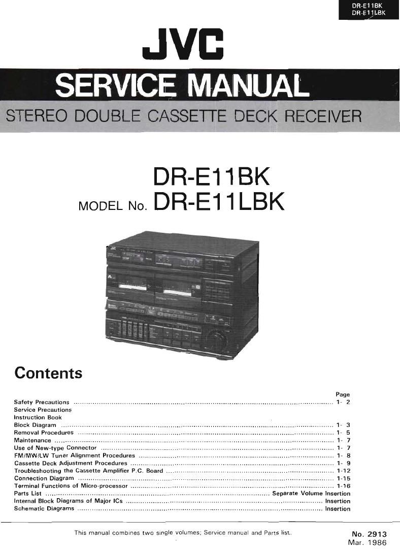
Jvc DRE 11 BK Service Manual
This is the 60 pages manual for Jvc DRE 11 BK Service Manual.
Read or download the pdf for free. If you want to contribute, please upload pdfs to audioservicemanuals.wetransfer.com.
Extracted text from Jvc DRE 11 BK Service Manual (Ocr-read)
Page 1
DR-El 1BK
DRvE 11LBK
JVB
SERVICE MANUAL
STEREO DOUBLE CASSETTE DECK RECEIVER
DR-E1 1 BK
MODEL N0. DR'E11LBK
Contents
Safety Precautions ..
Service Precautions
Instruction Book
Block Diagram ...........
Removal Procedures
Maintenance ..............
Use of New-type Connector .....................
FM/MW/LW Tuner Alignment Procedures
Cassette Deck Adjustment Procedures
Troubleshooting the Cassette Amplifier P.C. Board .
Connection Diagram ...........................
Terminal Functions of Micro-processor
Parts List .....................................
Internal Block Diagrams of Major ICs r, Insertion
Schematic Diagrams . . -- Insertion
.. 1-16
. Separate Volume Insertion
This manual combines two single volumes; Sen/Ice manual and Parts list. No_ 2913
Mar. 1986
Page 2
DR-El lBK
DReEl 1LBK
1-2
Safety Precautions
l. The destgn of this product contains special hardware,
many circuits and components speCIally for safety pur-
poses.
For continued protection, no changes should be made
to the original de3ign unless authorized in writing by
the manufacturer, Replacement parts must be identical
to those used in the original circuits. Servrce should be
performed by qualified personnel only.
2 Alterations of the design or CirCUitry of the product
should not be made. Any design alterations or additions
will void the manufacturers warranty and Will further
relieve the manufacturer of responsibility for personal
injury or property damage resulting therefrom.
3. Many electrical and mechanical parts in the product
have special safety-related characteristics. These characr
teristics are often not evident from visual inspection
nor can the protection afforded by them necessarily
be obtained by using replacement components rated for
higher voltage, wattage, etc. Replacement parts which
have these speCIal safety characteristics are identified
in the parts list of Service manual. Electrical components
having such features are identified by shading on the
schematics and by (A) on the parts list in Serwce
manual. The use of a substitute replacement which does
not have the same safety characteristics as the recornr
mended replacement part shown in the parts list in
Service manual may create shock, fire, or other hazards.
4. The leads in the products are routed and dressed with
ties, clamps, tubings, barriers and/or the like to be
separated from live parts, high temperature parts, mov
ing parts and/or sharp edges for the prevention of elec»
tric shock and fire hazard.
When serVice is required, the original lead routing and
dress should be observed, and they should be confirmr
ed to be returned to normal, after rerassernbling
5. Leakage current check
(Safety for electrical shock hazardl
After re-assembling the product, always perform an
isolation check on the exposed metal parts of the
Products (antenna terminals, knobs, metal cabinet,
screw heads, headphone jack, control shafts, etc.) to be
sure the product is safe to operate without danger of
electrical shock.
Do not use a line isolation transformer during this check.
0 Plug the AC line cord directly into the AC outlet.
Using a "Leakage Current Tester", measure the
leakage Current from each exposed metal part of the
cabinet, particularly any exposed metal part having a
return path to the chassis, to a known good earth
ground, Any leakage current must not exceed 0.5 mV
AC (r ms).
. Alternate check method
Plug the AC line cord directly into the AC outlet. Use
an AC voltmeter having 1,000 ohms per volt or more
senSitiVity in the following manner. Con-
necta1500 Q 10 W resistor paralleled by a 0.15 piF
AC-type capacitor between an exposed metal part
and a known good earth ground. Measure the AC
voltage across the reSIstor with the AC voltmeter.
Move the resistor connection to each exposed metal
part, particularly any exposed metal part haying a
return path to the chassis, and measure the AC
voltage across the resistor, Now, reverse the plug in
the AC outlet and repeat each measurement. Any
voltage measured must not exceed 0 75 V AC (r.m.s.).
This corresponds to 0,5 mA AC lr.m.s.l.
1 AC VOLTMETER
./ r (Havmg 1000 ohms/volt.
or more sensitivity.)
l-TO l
A 1., t A TVt
.s 7 .4, ,
Place this probe
i._i_x4~w L . ~nn each exposed
metal part.
Good earth ground
CHECKING VOUR LlNE VOLTAGE (Except for U.S.A., Canada, Australia, UK. and Continental Europe.)
Before inserting the power plug, please check this setting to see that it corresponds with the line voltage
in your area. If it doesnt, be sure to adjust the voltage selector switch to the proper setting before operating
this equipment. The voltage selector switch is located on the rear panel.
CAUTION Before selecting the "Voltage selector swrtch" to proper voltage disconnect the power plug.
(No.2913l
Page 15
DR-E1 1BK
DR-E1 ILBK
;_
OPERATION BEDIENLING
LISTENING TO BHOADCASTS 0R WIEDEHGABE VON RADIOSENDUNGEN
RECORDS ODER SCHALLPLATTEN
1 Press the POWER bufion 10 ON 1")af1ar 7_ Dan Lamslarkerefl er ml! Minimum seHen
ssnnq we thJmi-J knob to 'n mmum. und dann Um POWE HrScnalLer auf ON
2. 7" star to broadcdsls press the TUNER (A)dmcken,
human, 2, Zum Horen emer Sen'. 1 die TUNERA
3 TO SI 7 [c 2 AM "LW broaucast, 7" .,
[V U " \1 "AW/UNI I 'r 3, Z * r; . W \ N»Senders o'er]
471. > :(e "1 1" F'\ broznuast, press xhe AM JVVIK . " :,_;.7Hr 1
471, Z V v ' ' s i>" FMV
42. P1 7" 1 - .'
Nam:
Oln weak signal trans, set the FM MODE/ Hinweis:
MUTE buncn m MONO/OFF. FM broadcast.» O In Gahieten mi! achwachen Sendersigna-
wiH be heard in mom: but noise is reduced. len den FM MODE/MUTE-Scham" aul
MONO/OFF sullen, Die UKWSender warden
dann in Mono gehdn, abs! die Stbvwr'auschu
34nd reduzlert.
5 u- x v w. :' w; m
S! ' .
\ v 1 PM ')h.yod.m we FM m G, H mm
H H: - g . can wu w I
Presening to selected stations LKJ, vw \V\ fW -
671. mew ;s.7W£ 1pm. m ON I;) and V» H n KW .u
M k my" w" "Uun W_,J=_,... >7
6'2. 7 H "W M " N (W "V" " " " Balegung der Slatlonsaslen
673. " rzwu/v'r 3 671,15
" , v 4. 3 , w p
r , n . / , y z . , ,
v . . ,
l , ,
3 L, ~ )1 . . V
Note: ' ' 7 ,
'NO sound is output when me PRESET 87A '57 ' 1r .
TKDNS buttons are p1255€tfiVhiSIs m prevent x: . "' - ,, . \
noise and is no! a malfuncxion
I » r V W
Hinweis
. Bei Befsitigen der PRESET STATIONSTaslen
~ . » erlulgx heme Tonwcedergaba. Dies In keme
' v x v m ; \ ,2. Us Fehlfunklianl sondern diem der Unrer
41' , . L m druckung Von Skorgerauschen,
' ' ,3 I: n: , z
Note: , v
I A xulal 32 slatiuns (FM, AM (MW/LW)) can be 7 H - 1' <
press! by changmg me swing of [he PRESET
SELECT button [1 - a, 9 - n3)
7. 4
V 4 IV 1
. , V ' Hlnweis
A , 1 , . Ilnsgesamt kbnnen 32 Stations" [UKW, AM
, , 1 . H (MW/Lwll gespsicherl warden, wenn me
8 . I V . ._ _ PRESET SELECT-Taste umgeste'll wwd (1 -
, , , 3, 3.9-16)
; u < 7_ v , ,mm,
(No. 2913)
Page 41
DR-El lBK
DR-E1 1LBK
PARTS LIST
Contents
Main Pans Locations ................................................................................................................................... 2»2
Exploded View and Parts List . 2-3
Mechanism Assy .................. 2-7
Printed Circuit Board and Parts List ......................................................
l ENJ-OIOD Cassette Amplifier and Audio Amplifier P.C. Board Ass'y ..
I EMA-053D Tuner P.C. Board Ass'y .
I EMF-025. SEA P.c. Board Ass'y ,.
.241
.2-11
.2-15
.2-18
I ENE-030E] LCD Display and Operation Switch P.Cr Board Ass'y . 2~19
I ENJOOGLZ] Noise Reduclion P.C. Board Assy .......................... . 2.20
I ENJ-OO4IE Record Amplifier and Playback Amplifier P.C. Board Ass'y i 2-21
Packing Malerials and Part Numbers ........................................................ . 2-22
Accessories List ........................................................................................................................................ 223
(No. 2913) 2-1