Jvc CHX 450 Service Manual

This is the 38 pages manual for Jvc CHX 450 Service Manual.
Read or download the pdf for free. If you want to contribute, please upload pdfs to audioservicemanuals.wetransfer.com.

Page: 1 / 38
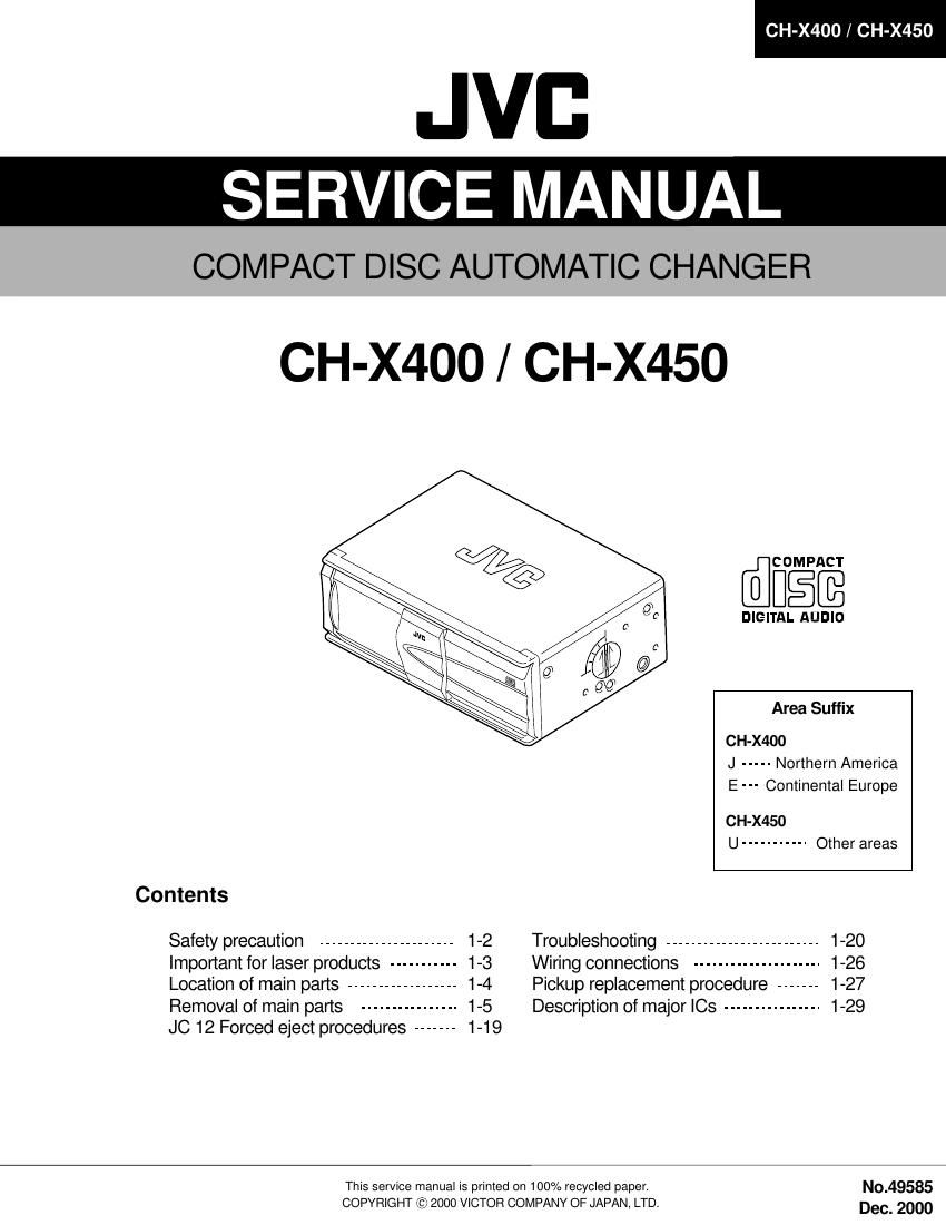
Jvc CHX 450 Service Manual

Extracted text from Jvc CHX 450 Service Manual (Ocr-read)


Page 1

CH-X400/CH-X450 1-2 ! Burrs formed during molding may be left over on some parts of the chassis. Therefore, pay attention to such burrs in the case of preforming repair of this system. Safety precaution ! Please use enough caution not to see the beam directly or touch it in case of an adjustment or operation check.

Page 2

CH-X400/CH-X450 1-3 Important for laser products 1.CLASS 1 LASER PRODUCT 2.DANGER : Invisible laser radiation when open and inter lock failed or defeated. Avoid direct exposure to beam. 3.CAUTION : There are no serviceable parts inside the Laser Unit. Do not disassemble the Laser Unit. Replace the complete Laser Unit if it malfunctions. 4.CAUTION : The compact disc player uses invisible laserradiation and is equipped with safety switches whichprevent emission of radiation when the drawer is open and the safety interlocks have failed or are de feated. It is dangerous to defeat the safety switches.5.CAUTION : If safety switches malfunction, the laser is able to function. 6.CAUTION : Use of controls, adjustments or performance of procedures other than those specified herein may result in hazardous radiation exposure. VARNING : Osynlig laserstrålning är denna del är öppnad och spårren är urkopplad. Betrakta ej strålen. VARO : Avattaessa ja suojalukitus ohitettaessa olet alttiina näkymättömälle lasersäteilylle.Älä katso säteeseen.ADVARSEL : Usynlig laserstråling ved åbning , når sikkerhedsafbrydere er ude af funktion. Undgå udsættelse for stråling. ADVARSEL : Usynlig laserstråling ved åpning,når sikkerhetsbryteren er avslott. unngå utsettelse for stråling. REPRODUCTION AND POSITION OF LABELS WARNING LABEL DANGER : Invisibie laser radiation when open and interlock or defeated. AVOID DIRECT EXPOSURE TO BEAM (e) VARNING : Osynlig laserstrålning är denna del är öppnad och spårren är urkopplad. Betrakta ej strålen. (s) VARO : Avattaessa ja suojalukitus ohitettaessa olet alttiina näkymättömälle lasersäteilylle.Älä katso säteeseen. (d) ADVARSEL :Usynlig laserstråling ved åbning , når sikkerhedsafbrydere er ude af funktion. Undgå udsættelse for stråling. (f) ! CAUTION Please use enough caution not to see the beam directly or touch it in case of an adjustment or operation check. Caution. This production contains laser component of higher laser class than Class 1. Top panel of the unit Gerateoberseite Panneau superieur de l"appereil

Page 6

CH-X400/CH-X450 1-7 Removing the fittings Removing the main PCB assembly 1. Remove the fixing screw (5). 2. Unhook the two catches (a) on the top edge of the fitting, then unhook the catches (b) at the left/right bottom edges. 1. Remove the power IC fixing screw (6). 2. Remove the four screws (7) securing the main PCB assembly. 3. Disconnect position motor wire connector CN504 from the main PCB assembly. 4. Disconnect sensor PCB assembly wire connector CN601 from the main PCB assembly. 5. Remove the flexible ribbon wire from CN502 on the traverse mechanism PCB assembly. When reinstalling the PC boards, refer to the reassembling procedures for protecting switches, etc.Catches (a) Catches (b) Fitting 5 7 CN6017 7 Fig. 10 Fig. 11 6 CN504 CN502

Page 30

CH-X400/CH-X450 1-31 Pin No. PORT Name I/O Function Active Pin No. PORT Name I/O Function Active 1 2 3 4 5 6 7 8 9 10 11 12 13 14 15 16 17 18 19 20 21 22 23 24 25 26 27 28 29 30 31 32 33 34 35 36 37 38 39 40LCDDA LCDSCK LCDCE AVSS ADCOUT NC AVREF1 NC NC CDCHECK EPROMDI EOROMDO EPROMCK LED BUS I/O BUS SI BUS SO BUS SCK NC NC NC NC NC NC BUSOUT CD ON PWR CONT POSMO+ POSMO- TRAYMO+ TRAYMO- BUCK VSS1 LSI RESET CCE BUS0 BUS1 BUS2 BUS3 NCO O O - O O - O O I I/O O I/O O O I O I/O O O O O O O O O O O O O O O - O O I/O I/O I/O I/O OH H H H H L LCD driver data output LCD driver clock output LCD driver chip enable output Connect to ground Power on Hi output. Low in stop mode. Unused output port Connect to 5V Unused output port Unused output port CD check mode input. Reset only. EEPROM data input EEPROM data output. Hi durring input. EEPROM clock input/output Lifter LED output JVC bus input/output control(Lo:input) JVC bus data input JVC bus data output JVC bus clock input/output Unused output port Unused output port Unused output port Unused output port Unused output port Unused output port JVC bus output CD power control Hi:on Power supply control output Hi:on Position motor control output Position motor control output Tray motor control output Tray motor control output CD LSI data clock Connect to ground CD LSI reset CD LSI chip enable CD LSI data 0(open drain) CD LSI data 1 (open drain) CD LSI data 2 (open drain) CD LSI data 3 (open drain) Unused output port41 42 43 44 45 46 47 48 49 50 51 52 53 54 55 56 57 58 59 60 61 62 63 64 65 66 67 68 69 70 71 72 73 74 75 76 77 78 79 80NC NC NC MAG IN TRAY IN TRAY OUT REST NC EMPH NC BUFF CONT TEST RUN NC NC NC MUTE STAGE NC EPROM CLF RESET REMOCON PWR DET PWR SW BUS INT EJECT NC VSS0 VDD1 X2 X1 IC XT2 XT1 VDD AVREF0 L SENSOR KEY1 KEY2 KEY3 KEY0O O O - O O I O O O O I O O O O I O I I I I I I I I - - O I - O I - - I I I I IL L L L H L L H L L L L Unused output port Unused output port Unused output port Magazine switch Lo:magazine inserted Tray retract switch Lo:retraction complete Tray extend switch Lo:extension complete Resr switch Unused output port Emphasis select output Hi:on Unused output port Buffer control output Test running input Unused output port Unused output port Unused output port Mute output. When reverse of earlier audio mute. Mute power OR output LCD,AD key,remote inhibit selector Low:inhidit Unused output port EEPROM clear input Functional only dunng reset Reset input (includes flash write in function) Remote controller signal input Memory power detect input CRTL+B detect input JVC bus com start interrupt input Eject key input Unused output port Connect to ground Connect to 5V Oscillater (4.19430 MHz) Oscillater (4.19430 MHz) Connect to ground Open Connect to VDD Connect to 5V Connect to ADCONT Linear sensor input(8 bit A/D input) Key input 1 (8 bit A/D input) Key input 2 (8 bit A/D input) Key input 3 (8 bit A/D input) Key input 0 (8 bit A.D input) 3.Pin function UPD780058GC-067