Jvc CAC 33 BK Service Manual

This is the 116 pages manual for Jvc CAC 33 BK Service Manual.
Read or download the pdf for free. If you want to contribute, please upload pdfs to audioservicemanuals.wetransfer.com.

Page: 1 / 116
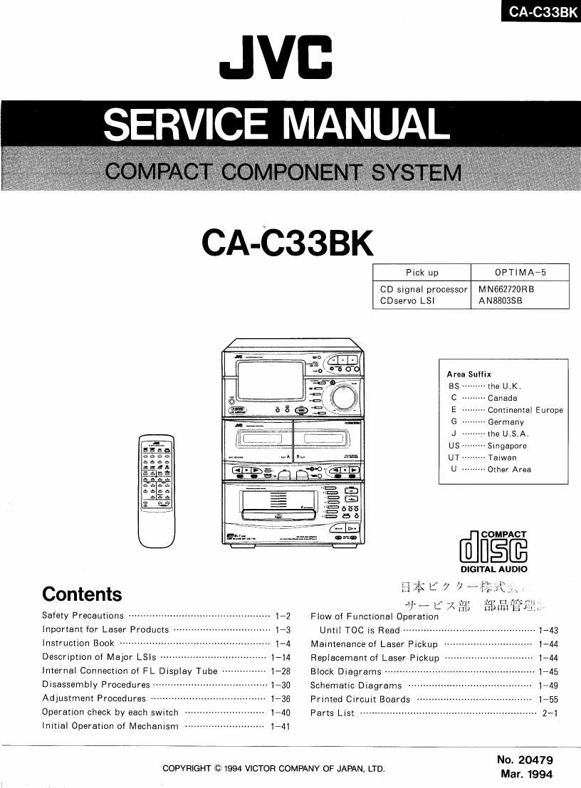
Jvc CAC 33 BK Service Manual

Extracted text from Jvc CAC 33 BK Service Manual (Ocr-read)


Page 1

JVB
SERVICE MANUAL

CA-C33BK

Pick up OPTIMA-5
CD signal processor MN662720RB
CDservo LSl AN8803SB
Area Suffix
BS - the UK
C , Canada
E - -- Continental Europe
G - Germany
J - --the U.S.Al
8 a , US> -- Singapore
aeéu mm- w M 37- UT- --Ta|wan
éeeé
fags U --------- Other Area
D553
e_e¢.a
d, e a b
ééfie
i a
COMPACT
DIGITAL AUDIO
ii .i l w r.
Contents "13$ t 7 if, it EM ,
17" 1: A M; tzliimb 41.;

Safety Precautions '- 1-2 Flow of Functional Operation

Important for Laser Products . 1-3 Until T00 is Read ............................................. 1_43
Instruction Book .................................................. 1-4 Maintenance of Laser Pickup .............................. 1-44
Description of Major LSIs ------------------------------------ 1-14 Replacement of Laser Pickup ------------------------------ 1-44
internal Connection of FL Display Tube --------------- 1-28 Block Diagrams --------------------------------------------------- 1745
Disassembly Procedures .. Schematic Diagrams .......................................... 1-49

Adjustment Procedures --
Operation check by each switch

Initial Operation of Mechanism ------------------------- 1-41


1-55
- 2-1

Printed Circuit Boards
Parts List --

COPYRIGHT © 1994 VICTOR COMPANY OF JAPAN, LTD.

No. 20479
Mar. 1994

Page 2

CA-CBBBK

--Safety Precautions

1.The design of this product contains special hardware and many circuits and components

specially for safety purposes. For continued protection, no changes should be made to the
original design unless authorized in writing by the manufacturer. Replacement parts must
be identical to those used in the original circuits. Services should be performed by
qualified personnel only.

.Alterations of the design or Circuitry of the product should not be made. Any design

alterations of the product should not be made. Any design alterations or additions will
void the manufacturer's warranty and will further relieve the manufacture of responsibility
for personal injury or property damage resulting therefrom.

.Many electrical and mechanical parts in the products have special safety-related

characteristics. These characteristics are often not evident from visual inspection nor can
the protection afforded by them necessarily be obtained by using replacement components
rated for higher voltage, wattage, etc. Replacement parts which have these special safety
characteristics are identified in the Parts rList of Service Manual. Electrical components
having such features are identified by shading on the schematics and by ($) on the Parts
List in the Service Manual. The use of a substitute repalcement which does not have the
same safety characteristics as the recommended replacement parts shown in the Parts List of
Service Manual may create shock, fire, or other hazards.

.The leads in the products are routed and dressed with ties, clamps, tubings, barriers and

the like to be separated from live parts, high temperature parts, moving parts and/or sharp
edges for the prevention of electric shock and fire hazard. When service is required, the
original lead routing and dress should be observed, and it should be confirmed that they
have been returned to normal, after re-assembling.

, Leakage currnet check (Electrical shock hazard testing)

After re-assembling the product, always perform an isolation check on the exposed metal
parts of the product (antenna terminals, knobs, metal cabinet, screw heads, headphone jack,
contorl shafts, etc.) to be sure the product is safe to operate without danger of electrical
shock.

Do not use a line isolation transformer during this check.

0 Plug the AC line cord directly into the AC outlet. Using a "Leakage Current Tester",
measure the leakage current from each exposed metal parts of the cabinet, particularly
any exposed metal part having a return path to the chassis, to a known good earth
ground. Any leakage current must not exceed 0.5mA AC (r.m.s.).

0 Alternate check method
Plug the AC line cord directly into the AC outlet. Use an AC voltmeter having, 1,000
ohms per volt or more sensitivity in the following manner. Connect a 1,5000. 10 W
resistor paralleled by a 0.15 ,uF AC-type capacitor between an exposed metal part and a
known good earth ground.

AC VOLTMETER

bu}

Measure the AC voltage across the resistor @ (Having 1000
With the AC voltmeter. ohms/volts, g
Move the resistor connection to each exposed 0 °_ 0' "0! VsmVWJ
metal part, particularly any exposed metal part
having a return path to the chassis, and 0,15,1F Ac TYPE
meausre the AC voltage across the resistor. -||-
Now, reverse the plug in the AC outlet and PI: this
repeat each measurement. Any voltage M >gg3heefigosed
measured must not exceed 0.75VAC (r.m.s.). 15°0n10W metal part.
This corresponds to 0.5 mA AC (r.m.s.). Good earth ground

-Warning

. This equipment has been designed and manufactured to meet international safety standards.
. It is the legal responsibility of the repairer to ensure that these safety standards are

maintained.

. Repairs must be made in accordance with the relevant safety standards.
, It is essential that safety critical components are replaced by approved parts.
. If mains voltage selector is provided, check setting for local voltage.

1-2 (No.20479)

Page 10

(GLVOZ'ON) O l-l

Aulc Edi! Recordlngz

lmrodufllon

Auto Edll Hocovdlng:

Slap by slep

a

Program Edit
Recordlng: Step by
59?

Aulo Edit Recording

Uxillg Auln Edll. you CHI] recon! the CD Hacks w l'l| ml: rdpc. on u Sclcumn isn| cul 0H Aum Edll Is one MLIIC hcsl ways
lo copy all ol n CD onlo a rope,

AumEdll programs lhc CD lurks lll \hc numerical older To prevent lhc cm! 0| me la lr'dck on "It: ('mlleldc from bclng
culol1.llrc lasl Irdck on pic from srdc r. d Io In on me rcmuiorng lope lengllr

I Prepare CDs [Soc page ll 1

2. Ser me sound efl'ecl mode il you wdnl.

3. Press Lhe EDXT bulum on me CD pldycl rcpcdlcdly um "A EDIT' lighlo up on me display.

4. Press roe SEARCH/EDITTIME I« or muuuon o« or »r bulllm on the Remote ronlrollcrl lcpcalcdly lo scl
Ihc rape lengrlr,

cut a drl'rercnr lengrlr of rope Irorn ren posrroilincs pr ogrrrorned rnro Inc CA» BK: 40. 4o. 50. 4.
hula: using me SEARCH/EDITTIME H4 0| m buulln (K1Irr

CI You can ,
60, 64. 7D, 74, 80. 90, Cycle through |hc
m on me Rcrnole controller)

I- I I I- 46%50a54am4434
L. -l D l->40---90<-30<-7d<-7oj

5 Press rnc SIDE AIE oouon on rnc CD plnyer
o. Sclecr n drse wrllr rnc doc oouons (I lo 6 nod PI.
Tlro dlsplzly snows whlch rrucks wlll go on ma lronl srdc (A) and Much on the reverse side (B).
7 Inserrr blank or ernsolrlc en. no In deck E
a ll you wunr ro record on hmh shins ol roe upc. pmss llrc REVERSE MODE hullnn on [he cnsscuc deck so rnor
Ihc REVERSE MODE mdrcoror IlghlS up.
a. Press rlre CD REC START onuon on [he one deck.
Tnc Uml wlll nurornuucally nzwlllLl rlrc lope Io ure bogrnorng or Inc Tom ode. creole o lo second blank. luro on me
CD and sun recording (A ll) .wcond blnnk rs also crenred on Iha heglnnlng ol Ine mvclsc srde.i

To stop any film: during lhe recording process
Press are I lruuon on deck E or l/(ANCEL ouuoo on file CD plnyer

To exll edlt mode nad delete the program
Press are PLAY MODE bullun so AEDIT' is no longer Ilghlcd on ore drspluy one Unil mosr no In slop mode ;

Usrng Ilrc Aulo Edir, you can program up to lo rrroks Ior each solo or lhc rope. and runner program n Huck rne
numlrer of wh *h on Ilre disc ~ rearer rlron 31

Program Edit Recording
Using Progrurn Edu. you can record only llrc CD lrucks you wdnl.dlld lrl Ilrem oolo Ilre rope. Program Edins one or Llre
besr woys or make u urpc ul only your loyounle songs.

1. Prepare CDs (See page x J
2 Ser rlre sound ollecr mode d you wnnr
3. Press the EDIT huuoo on use CD player repenredly rrnnl P, EDIT" llghls up on Ilre display.
4 Press Ihe SEARCH/EDIT TIME m or m nouon (m or m huluro on Lhc Remote conrroller) repealcdly lo M
Ihe rope lengur
D You can selecr 8 Memo leogln ol lupe lrom len possibiliues programmed imo Ihc CAVCESBK: 40. 46. 50. 54.
so. 64. 70. 7A. 30. 90. Cycle rlrrougn rlrese coorccs usrng me SEARCH/EDIT TIME «4 orw humor («4 or

m on rlre Rernole controller)
[_ / I [_ [:45 ->so~->544-60~>64:l
I -[ [-7 40.7 so<- eo<- 7A<- 70

[5

Tape Io lave dubbing:

Introductlon

Regular speed
dubbing: Step by s1ep

16

5. Press rlre SIDE AIS broom and sclocl Ihc lrdcks you Want Io record on me lronr ode (A),
By using Ihe Unit

(I) Sclccr a doc WIlh Ilrc disc hullum [1 lo o and PI. Assoon so dl

up on rlrc dis lay lryon wnnr all rho lrdcks on Inurdrsc Io mum}. slop slop (2]

(21 To ScchL mdlyrdurl lrocks From me oclcclcd drrc (us number rs rodrcorod hy rlre arrow on llre disployl. press no

me SEARCH/EDIT TIME I44 or »I bulk)".
(31 Press Inc MEMORY humor
(4) Repeal slcps l1) , (3) unril you lroye colored all me Irocks you warn.
By using Ihe Rerrrole conlmfler
(l) Presr Inc CD CHANGER
(2) Sclccl a disc wnh Ilre numeric keys [1 lo 6 and P7.
I3) To selccr indrvrduol lrdckx from me sclecred dl\c enrer coco number by prusslng rlro (D II) KEY nod using
lhc numc keys (I In loaod +10).
3 You c i also use Ilre I44 or »1 lo selecl tracks
(4) Repeal I l) , .Il uolil you have enlercd all me \rdck. you wool Io prognrm
D lrlhe lolul playing Irmc no me l'ronlsrdc (Alcxoccds on» rape longrlr lor our dr: lrc drsploycd exec
lime bllnks Dunng recordmg. me losl lrdck on Ilrrs ode wrll he recorded lad p our or rlru end orlne lope.
o. Press the SIDE A/B humln ond .xclccl ore rrucks you wool or record on or.» reverse side (E)
Selecl me Iraclrs us you em on suit my.
a moo rorol pldylng lone Ior ore reverse sldc (E7 exceedslhc rope Ienglrr for do srde. lhe displayed exc ~ployrng
umc hunks During lccnrdmg. rlrc l I lrdck on rlns srde wrll he recorded ladlng our or Inc cud or me lope
7 loved a hl'dnk or cranhlc c one in deck B
CI Ilyou wool Io record on noun srdcs ol roe rape. press roe REVERSE MODE onuon on Ilre
lhc REVERSE MODE rndrcoror llghLS up
3 Press the CD REC START onuon on roe cusscue deck
The Unl|w1llduwmullcdlly rcwrnd rlrc rrpc ro rlrc bcglnlmlg oI rlre lronr sidecrcnrc n 10 second olonk. mm on me
CD and sun recording, (A 10 second blank rs also creored on me hcglnnlng or rlre rcvcnc srdc I

||c deck 50 mm

To slop any time duing Ihe Incoming process
Press me I button on deck E or I/CANCEL bullon on ore (D plnycr

To exit edit mode and defele llre prulgnm
Press the PLAY MODE bulllm SO P. EDIT" Is no Ixmgm Ilghlcd on [he dlsplny (Ills: Uull musl bc In map mode I

D II you clroose wrong nooks dllrmg pmgrdmmlng. press rlre l/CANCEL ouuoo on lhc CD player. Eocu limo
you press rlre burron, rlre I: nosen rrock rs dclclcd lrom rho program.

a Uslnglhe ngmm Edn. yon can pmgmm up or lélrdckx Ioreaclr side orme urpc. nod cIlnnm progrnm o lmck
one number orwlrrclr on rlrc drsc rs gmalcr man 31.

a llyouwonlromakesomecnnngesrnprogrornolrcrslorungrecerdmg.makesorerlrnrrned pluyissnownrp
me Iruuks for me Ironl srdc (A) when you rcslorl recording. Ilnol. press Ilre SIDE A/B lonron

Tape tu Tape Recording (Dubbing)

Recordmg Irorn one rape ro anolhcr is lled duhomu.
You can dub olregrrInrspecd lor Inc ocsl pr hlequolrly. or willr r shghl Io
wun nign speed o lakes only room One-half rlrc me u) copy a rope
D To dub hulh sides of 11 hips. ohm [mm sldc A for DO"! deck A and chk B, and press the REVERSE MODE so
our Ihc REVERSE MODE rndrcaror llghls up
a Ir rs prelernolc rlrnr rlrc rypc olrupe (Normal or Clog) you record Iron Ire rlrc some as roe rypo you rccord euro

In sound quolily you can duhdl hlgh speed.

Regular Speed Dubbing

I Inserl a source casscue you wool m copy Irorn rnur deck A lrorn playback

2 Ins-en a blrnlr orernsaole e do you wool to copy onlo rnlo deck B lor recording,
3 Press Ilre REC PAUSE hullull on duck B.
4 Press lhc > bullun [or <1 hullorr) on deck 3,

Recordlng suns.
. To advance lhc lender upc one oegmning oldie lane on whlch you cunnol rccold). son recording Ind and wail
«hour It) seconds bcl'ore snoring door A.
5 Press rlre l> moon (or <1 hullOll) on deck A
Deck A soru playrng.

To stop any time durlng the dobolng process
Press me I lrnoon on born deck A and deck 3

D'VD

xclcucd, n is rocrnorr/od and AL lrglrls w

Page 24

CA-C33BK

I LA1266A( |C104) : FM AM IF AMP8IdeteCtor


I. The main function descriptions
(l) Amplify and detect of FM intermodulation frequencies.
(2) It has local oscillator and mixer for AM, and amplify the AM-IF signal.
2. Top View 3. Block Diagram
v AM AM AM
FM-IF [:1 14 film-056 out Mix IF IF 5:) IF FI-n Bypass FM-DET Vcc
5 [:2 23 AM~OSC
4::3 zzjvm r-E'J-E--E-- --- --- - ------ "1
GND 4 21 :IAM-In : :
_ E 5 20 JAM-Mix
x- 3: C6 Is JAM-AGC i I IF aufler IF BuflerH FM-IF 00 H F0 AmP- HE PM Out
v 7 IsjAM-IF l |
Sfé EB 17 3AM Adj. : I-H: FM AFI:
FM NC [9 16:]FM Adj I I
PM [:10 I5 :IAM out : E AM out
AM-IF E11 |4JNAR SM I .
whom :12 13 :Ismo i i
I I
l I
I LED I
: S-Mater 5- Meter Driver Q9. Tuned mu.
: Bandwidth _:
_ _ _____ ___ ___ ______ nose-w
LET wilih - 5..-.
AM AM-OSC AM-OSC NAR AG AM FM GND
«in in out SM Adj Adj
4. Description
Pin No. Symbol I/o Description
1 FM IF I This is an input terminal of FM IF Signal.
2. 3 Bypass --- Bypass of FM IF Amp.
4 GND -- This is the device ground terminal.
5, 6 FM DET --- FM detect transformer.
7 V --~ This is the power supply terminal.
8 SIGNAL 0 Mute drive and signal stop drive output when tuning. Active Low
9 FM AFC 0 This is an output terminal of voltage for FM-AFC.
10 FM IF 0 When the IF REQ signalof IC102(LC7218) applies to pin13, the signal of FM IF outputs.
11 AM IF 0 when the IF REQ signalof IC102(LC7218) applies to pin13, the signal of AM IF outputs.
12 FM out 0 FM detection output.
13 STRQ I The IF-signals come out from pinIO (FM-IF) or pinil (AM-IF) while this terminal goes to "High.
14 NAR SM --- Control the Bandwidth of AM signal meter.
15 AM out 0 AM detection output.
16 FM Adj .._ For adjust the stop level (or mute level) of FM.
17 AM Adj -- For adjust the stop level (or mute level) of AM.
18 AM-IF | Input of AM IF Signal.
19 AM-AGC I This is an AGC voltage Input terminal for AM.
20 AM-MIX O This is an output terminal for AM mixer.
21 AM-IN I This is an input terminal for AM RF Signal.
22 V.REF --- Control the Band-width of FM signal meter.
23 AM-OSC This is a terminal of AM Local oscillation circuit.
24 Aug-35C 0 AM Local Oscillation Signal output.

I L31639-CV(|C465) : Motor Driver

m [I V E 0U IN 1 IN 2 OUT 1 OUT 2 MOTOR
GND l2 ii V H L H L CLOCKWISE
L H L H COUNTER-CLOCKWISE
V<°m E 3] C H H OFF OFF WAITING
2 E 3] OUTZ L L OFF OFF WAITING

1-24 (No.20479)

Page 38

CA-C33BK

3. Electrical Adjustments

In principle, the adjustments should be made in the following sequence.

(Make the following adjustments after adjusting the head azimuth.)

Adjustments marked with an asterisk (') should always be made after the head is replaced OdBS =0.775V.
- Adjustment Standard
Ite Ad ustment Method
m J Location Value Remarks
1 Tape 1. Connect a frequency counter to the DOLBY
Speed TP(figure 3) and play back VTTA712. _

2, Normal speed Adjustment
Playback deck B to adjust the semi-fixed
resistor R539 on ENE-179-3. R539 3,000 Hz

t 10Hz

3. Confirm the normal speed of deck A
Play back deck A to confirm that the
difference between deckA and deck B is
within i51Hz.

4. High-speed confirming 6,000Hz
Play back deck A in high speed dubbing and :GDOHZ
confirm that the counter indicates BOOOHz.

* Standard level 1. Connect an electronic voltmeter to the DOLBY DeckA 1) The playback level varies when
2 (Playback TP(figure 3)_ L: R211 ~4st the head is replaced so should
Level) Play back VTT-724 (1 kHz: -4st) to adjust R: R212 (483) be adJUSEd- ,
the semi -fixed resistors. Deck B 5.6 an electronic voltmeter
L: R243 With an impedance of 100 kn
R: R244 01' more.
* Playback 1. Connect an electronic voltmeter to the DOLBY Deck A
3 Frequency TP (figure 3). l: 23%: 341;? ..
: m
9590" 2. Play VTT-703L(10kHz: -10st) and adjust k l )
semi-fixed resistors to obtain the standard 39:23:,
values. R: R236
* Recording 1. Connect a frequency counterto the BIAS L311 105kHZ -
4 Bias TP(figure 3),and perform a recording with no +10kHZ
Frequency signal to adjust bias frequency. ' SkHz
* Record/Play 1. Supply (Hz and 12.5kHz signals with ZSmV to L R3 1 Otgda Refer to figure 2 bejew.
5 Frequency AUX terminals respectively to record them. ' 0 m3; 1) The recording and playback
(Bitesponse t) 2. Connect an electronic voltmeter to the DOLBY R2 R302 as the "mug; reiponsedof :h: b
Ias curren ~ - casse e ec are a Jus e y
TP (figure 3) to confirm the recorded values. standard. adjusting the bias current.

3, If the values are not satisfied ,adjust the serni~ 2) Perform the adjustment with
fixed resistors and record the signals again to normal tape and confirm that
confirm the values. the values are within the

range for metal tape.
* Record 1. Input a l kHz(250mV) signal to AUX terminals Adi-St With "0""13' tape Md
6 lPlayback and record it on the left and right channels . L: R321 -55st make sure that the left/right
Sensitivity 2. Connect an electronic voltmeter to the DOLBY R R322 (4 V) level difference '5 10 ° less
TP (figure 3) to confirm the recorded levels. ' m

3. If the values are not satisfied, adjust the tldB
semi-fixed resistors and record the signal again
to confirm the values.

Response With a small bias current
(dB)

R301 (L)
R302(R)

(- \y Increasing

Decreasing
in high frequency
I

in high frequency

Optimum level

With a large bias current

1-38 (No.20479)

100Hz 1kHz

Figure 2

12.5kHz ->Frequency