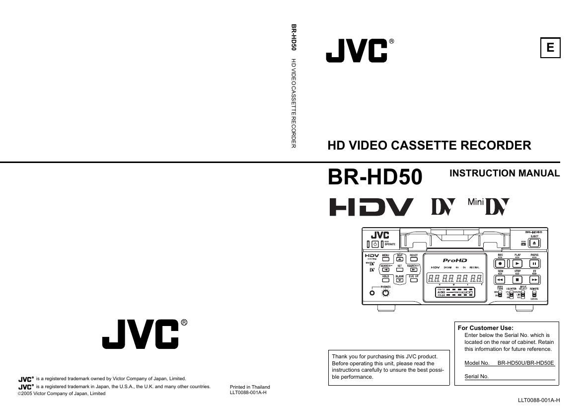
Jvc BR HD 50 Owners Manual
This is the 92 pages manual for Jvc BR HD 50 Owners Manual.
Read or download the pdf for free. If you want to contribute, please upload pdfs to audioservicemanuals.wetransfer.com.
Extracted text from Jvc BR HD 50 Owners Manual (Ocr-read)
Page 1
OSCI H'88
83080338 EILLEISSVO OEIGIAGH
®
HD VIDEO CASSETTE RECORDER
®
Jvca is a registered trademark owned by Victor Company oi Japan, Limited.
JVE is a registered trademark in Japan, the U.S.A., the U.K. and many other countries.
@2005 Victor Company of Japan, Limited
Primed in Thailand
LLT0088-001A-H
BR-H D50
INSTRUCTION MANUAL
Fl Dv DY MiniIhY
JVI:
[] m
an MEN"
4;; D E ProHD
HDV nvcm w 50 mm
a
: r:
ms
For Customer Use:
Thank you for purchasing this JVC product.
Before operating this unit, please read the
instructions carefully to unsure the best possi-
ble performance.
Serial No.
Enter below the Serial No. which is
located on the rear of cabinet. Retain
this information for future reference.
Model No. BR-HD50U/BR»HD50E
LLT0088-001A-H
Page 2
IMPORTANT SAFEGUARDS
FPNT
.0?"
10.
11.
12.
13.
14.
. Never push objects of any kind into this appliance through cabinet slots as they may touch dangerous volt-
16.
17.
18.
19.
Read all of these instructions.
Save these instructions for later use.
All warnings on the product and in the operating instructions should be adhered to.
Unplug this appliance system from the wall outlet before cleaning. Do not use liquid cleaners or aerosol
cleaners. Use a damp cloth for cleaning.
Do not use attachments not recommended by the appliance manufacturer as they may cause hazards.
Do not use this appliance near water - for example, near a bathtub, washbowl, kitchen sink, or laundry tub,
in a wet basement, or near a swimming pool, etc.
Do not place this appliance on an unstable cart, stand, or table. The appliance may
fall, causing serious injury to a child or adult, and serious damage to the appliance.
Use only with a cart or stand recommended by the manufacturer, or sold with the
appliance.
Wall or shelf mounting should follow the manufacturer's instructions, and should
use a mounting kit approved by the manufacturer. .
An appliance and cart combination should be moved With care. Quick stops,
excessive force, and uneven surfaces may cause the appliance and cart combina-
tion to overturn. l-
Slots and openings in the cabinet and the back or bottom are provided for ventila- 53125;;
tion, and to insure reliable operation of the appliance and to protect it from over-
heating, these openings must not be blocked or covered. The openings should
never be blocked by placing the appliance on a bed, sofa, rug, or other similar surface. This appliance
should never be placed near or over a radiator or heat register. This appliance should not be placed In a
built-in installation such as a bookcase unless proper ventilation is provided.
This appliance should be operated only from the type of power source indicated on the marking label. If
you are not sure of the type of power supplied to your home, consult your dealer or local power company.
For appliance designed to operate from battery power, refer to the operating instructions.
This appliance system is equipped with a 3-wire grounding type plug (a plug having a third (grounding
pin). This plug Will only fit into a grounding-type power outlet. This is a safety feature. if you are unable to
insert the plug into the outlet, contact your electrician to replace your obsolete outlet. Do not defeat the
safety purpose of the grounding plug.
For added protection for this product during a lightning storm, or when it is left unattended and unused for
long periods of time, unplug it from the wall outlet and disconnect the antenna or cable system. This will
prevent damage to the product due to lightning and power-line surges.
Do not allow anything to rest on the power cord. Do not locate this appliance where the cord will be
abused by persons walking on it.
Follow all warnings and instructions marked on the appliance.
Do not overload wall outlets and extension cords as this can result in fire or electric shock.
PORT/XE} CART WARMNG
lsvrvhol mm by RETACi
age points or short out parts that could result in a fire or electric shock. Never spill liquid of any kind on the
appliance.
Do not attempt to service this appliance yourself as opening or removing covers may expose you to dan-
gerous voltage or other hazards. Refer all servicing to qualified service personnel.
Unplug this appliance from the wall outlet and refer servicing to qualified service personnel under the fol-
lowmg conditions:
a.When the power cord or plug is damaged or frayed.
b.lf liquid has been spilled into the appliance.
c.lf the appliance has been exposed to rain or water.
d.lf the appliance does not operate normally by following the operating instructions. Adjust only those con-
trols that are covered by the operating instructions as improper adjustment of other controlsmay result
in damage and will often require extensive work by a qualified technician to restore the appliance to
normal operation.
e.lfthe appliance has been dropped or lthe cabinet has been damaged.
f. When the appliance exhibits a distinct change in performance - this indicates a need for service.
When replacement parts are required, be sure the service technician has used replacement parts speci-
fied by the manufacturer that have the same characteristics as the original part. Unauthorized substitu-
tions may result in fire, electric shock, or other hazards.
Upon completion of any service or repairs to this appliance, ask the service technician to perform routine
safety checks to determine that the appliance is in safe operating condition.
Page 30
CONNECTION
Connecting video signals
Video output, e CRICamera
Digital input ,- Analog input _!
HDV/0V Y/C Composite
Digital output Y/C Composite
HDV/UV I-Analog output _1
Video input, VCR
Turn off the power before making connec-
tions.
I Input signal
The input video signal is selected with the
INPUT SELECT switch on the front panel.
0 To input analog video signals
Use the LINE [N terminal or Y/C IN terminal.
- LINE IN terminal:
Inputs composite video signals.
Connect a BNC cable.
- YIC IN terminal:
Inputs Y/C separate video signals. Connect
an S video cable (4PIN).
When a wide screen ID signal is input, the
ID signal is recorded.
E-26
HDM| OUT HD/SD Digital
HD monitor
->
->
_-
' (a
t=l HD/SD Analog
COMPONENT
OUT Monitor
0 To connect digital signals
Connect HDV signals or DV signals to the
IEEE1394 terminal.
Connect an IEEE1394 (SPIN) cable.
HDV signals using 720p format can be input.
HDV 720p format:
720/30p, 720/24p, 480/60p
720/25p, 576/50p
- The IEEE1394 switch located on the front
panel needs to be set, according to whether
the video format is HDV or DV.
- Digital audio is also input from the
IEEE1394 terminal.
- Power is not supplied via the IEEE1394 ter-
minal.
Attach the supplied filter to the IEEE1394
cable. (@Page 29)
For more information on the IEEE1394 termi-
nal, refer to page 18.
Page 36
RECORDING/OUTPUT SIGNAL FORMAT
Inputting analog signal
I Recording and output terminal video/audio signal format when inputting analog
signal
Input terminal
Output terminal
LINE
IN
1Analog video
A/ D con»
Tape: nv recording (480i. 576i
Digital video
.J
version
Digilal
EE video
AUDIO IN A"a_'°9
mo aim au lo
oon- ,
version
: audio
:Dlgil'al" O O
Video signals
________ Audio signals
"9" OUT SD Digital video
-- 0:- --- Digital EE video E] (480i)(576i)
: 4 Digital audio
5 , Digital EE audio I COMPONENT
f- - ------------------------------ ' BUT
I v @
Digital EE I Analog EE video SD Analog oom-
= -~O wig???
E PR @9
: Front panel
I IEEE1394 switch
I IEEE1394 DV Digital video
: (480i) (576i)
I @: DV 3 A @ Digital audio
I format I
I o Digital EE audio I
. _ _. i ________________________________ .
I '6': Composite
5 I - con- Analog EE video video (480i)
: P (576')
I we
: . OUT Y/C separate
: Analog EE video video (480i)
: -verslon . (576i)
I A I EE d' Aunio our
'_ ________ na ?9____a_u_10_ _________ _. W W Analog audio
_ Tape HDMI OUT terminal .
InputVldeo Model Input recording IEEE1394 COMPONENT OUT LINE OUT terrrllnal
format Signal terminal . YIC OUT terminal
format terminal
A | U model 480/60i 480/60i 480/60i 480/60i 480/60i
na 0
g E model 576/50i 576/50i 576/50i 576/50i 576/50i
E-32
Page 62
TIME CODE
Displaying the time code
This unit records or plays back the time code and user's bit. Whether to record the user's bit can be
selected with U-BIT in the TC/UB/CLOCK [2/2] Menu screen (only for E model). With the time code
function, accurate positions of the tape contents can be specified to enhance editing precision and
operation efficiency. During recording or playback, the time code and users bit are displayed on the
monitor or the Counter display.
Status display (Monitor)
TCG : Time code generator data
DV 3 2 K CH ~ 1 / 2
TCR : Time code reader data
DTCG : Input time code data from
the IEEE1394 terminal
UBG : User's bit generator data
UBR : User's bit readerdata STANDBY-0| FT
T CR 0 2 . 0 0 0 0 :
DUBG : User's bit input data from I
, Framing mode
(for NTSC only)
: (colon) : Non-drop frame
.(dot) : Drop frame
the IEEE1394 terminal
Time code/Users bit display
During playback
During DV input
During recording and stop mode: Data of time code generator
Data recorded on the tape
: Data selected with TC DUPLI.:
DV in the TC/UB/CLOCK
Menu screen
I To display the time code] users bit, perform the fol-
lowing settings.
- Set DISPLAY in the DISPLAY Menu screen to ON or AUTO.
-> The status is displayed on the monitor.
- Set TIME CODE in the DISPLAY Menu screen to ON.
-> The time code, users bit or CTL counter is displayed at the
counter display section of the status display.
- Select the counter display mode with the COUNTER switch
on the front panel.
To display the time code, select TC.
To display the users bit, select UB.
Checking the data of time code generator
When it is in the STOP mode, press the REC button and the data
of the time code generator will be displayed while the button is
held down.
E-58
DISPLAY Menu screen
---DISPLAY-»-
DISPLAY 0N
COUNTER POSI LOWER-R
I>TIME CODE 0N
VTR MODE ON
TAPE REMAIN 0N
TIMEIDATE DATEYTM
AIY INFO ON
DATE STYLE DDIMMIYY
TIME STYLE ZlHDUR
PAGE BACK
The display position can be
selected.
COUNTER switch
Page 69
I To display the Menu screen at the next level, bring
the cursor to NEXT PAGE and press the SET or >
button.
I To return to the previous Menu screen, do one of the
following actions.
- Press the > button.
Or
- Select PAGE BACK and press the SET or > button.
4. To return to the normal screen, do one of the following
actions.
- Press the MENU button.
Or
- Select EXIT in the TOP Menu screen and press the SET or
> button.
Menu sc een c nter d'splay
The counter display shows menu code numbers when setting
menus.
0.1 0.5 0.0
I- Setting value
items
Menu screen
(Example) 01: SYSTEM Menu screen
- Menu display: Flashes when the TOP MENU screen is dis-
played.
- Items : Flashes when each menu screen is displayed.
(No settings are selected yet.)
- Setting : Flashes when a menu item is selected and the
setting on the monitor display is flashing.
SYSTEM [1/2] Menu screen
FADV DV 2ND
:DV oFF
PAUSE TiME 303E
NS P TiME 5MiN
AusE MODE STEY
EV FuNc VAR!
oFF
M
GE
0
0
P
. K
AT
PA
BA
SYSTEM [2l2] Menu screen
E-65