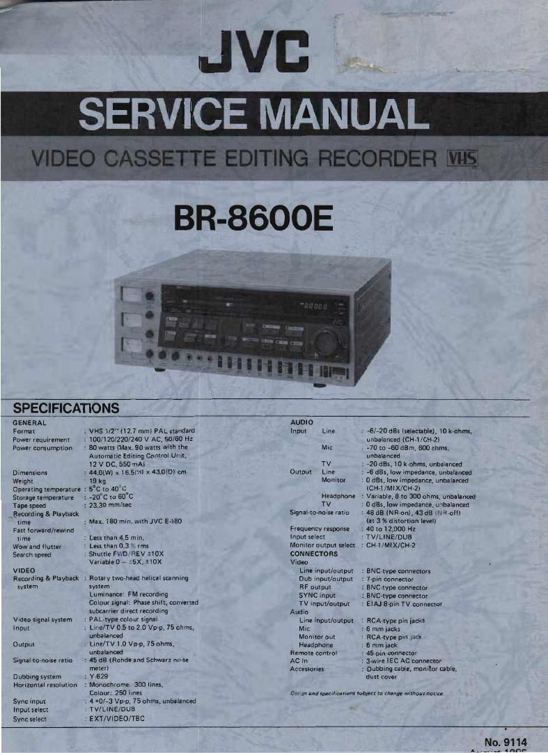
Jvc BR 8600 E Service Manual Part 1
This is the 109 pages manual for Jvc BR 8600 E Service Manual Part 1.
Read or download the pdf for free. If you want to contribute, please upload pdfs to audioservicemanuals.wetransfer.com.
Extracted text from Jvc BR 8600 E Service Manual Part 1 (Ocr-read)
Page 1
SPECIFICATIONS
GENE RAL
Format : VHS 1/2" (12.7 mm) PAL standard
Power requirement 1 100/120/220/240 V AC, 50/60 Hz
Power consumption : 80 watts (Max. 90 watts with the
Aulamllc Editing Cnntrol Uflll,
12 V DC, 550 MA)
Dimensions r 44tO(WI x 16.5lHl x 43,0(Dl cm
Weight 19 kg
Operating temperature : 5°C to 40C
Storage temperature : -20"C to 60°C
Tape speed : 23.39 mm/sec
Recording 81 Playback
time : Max. 180 min. wrth JVC E480
Fast lorward/rewind
time ' LEss than 45 min.
Wowand flutter .' Less than 0.3 n rms
Search speed : Shuttle FWD REV tIDX
Variable 0 e :5x, 2le
VIDEO
Recording & Playback : Flotarytwo-head helical scanning
system system
Luminance' FM recording
CDlour slgnai' Phase shift, converted
subcarrier direct recording
Video signal system : PAL-type colour signal
Input : Line/TV 0.5 to 2.0 Vp-p, 75 ohms,
unbalanced
Output Line/TV 1.0 Vp-p, 75 ohms,
unbalanced
Signal-tannin ratio ' 45 dB [Rahdeand Schwarz nu se
meter)
Dubbing system : Y-629
Horizontal resolution : Monochrome; 300 lines,
Colour: 250 ilnes
Sync input . 4 +0/-3 Vup. 75 ohms, unhalanoed
Input select TV/LINE/DUB
Sync select : EXT/VlDEO/TBC
AUDIO
Input Line . ~6/-20 st (selectable), ID k
Mn: . -70 to -60 earn, 300 ohms,
unbalanced
TV : >20 st, IOk-ohms, unbalanced
Output LlnE : -6 ass, low impedance, unbalanced
Monitor . U st, low impedance, unbaiinced
(CH4 /MlX/CH»2)
Headphone : Variable. 3 to 300 ohms, unbalanced
TV : 0st, low impedance,unbalanced
Signal-tuvnolsfl ratio : 48 dB (NRonI, 43 :15 W all)
(at 3 36 distortion levell
Frequency response : 40 to 12,000 Hz
Input select : TVILINE/DUB
Monitor output select 2 CH-l/MlX/CH-Z
CONNECTORS
Video
Line input/output : ENC-type connectors
Dub input/output : 7~pin connecmr
RF output : ENC-type connector
SYNC input : BNCvtvpe connector
TV Input/output '. EIAJ Spin TV connector
Audio
Line inputluutput : RCA-type pin jacks
Mil: : 6 mm jacks
Monitor out : RCA-type pin lack
Headphone . 6 mm jack
Remote control : 45»pin connector
AC In : 3-wire lEC AC connector
Accessories : Dubbing cable, monitor cable,
du5t cover
0mm and Suecifrcdnons mime: (a change without norm.
Page 2
COPYRIGHT © 1985 VICTOR COMPANY OF JAPAN, LTD.
Page 19
1.6
COLOR SIGNAL PLAYBACK SYSTEM
The color signal playback system performs essentially
the opposite function as the recording system. in addi-
tion, however, important corrections must be performed
for color signal frequency and phase errors introduced
by variations in tape speed and head rotation, and
elasticity of the tape.
Fig. 146 indicates an abbreviated block diagram of this
system.
Though a Iowpass filter, the down converted color Signal
goes to the main converter. At this time, the down con-
verted color subcarrier (Fc) contains an error component
(40 Fh' + 1/8 Fh i- Af) due to mechanical factors of the
heads and tape. Fh varies with the tape speed as Fh i
AFh. At is the instantaneous error caused by head
rotation irregularities and tape elongation and contrac
tion.
The 40 Fh' frequency deviation component is com-
pensated by supplying the video output signal to the
horizontal sync separator, multiplier and phase shifter,
and 40 Fh to the sub converter. This forms the AFC
(automatic frequency compensator) loop.
Alimuth Video
head : 6
i, 4w Warsaw
in the APC (automatic phase compensator) loop, the
1/8 Fh' 1 At phase error component is compensated by
comparing the burst component of the up converted
playback color signal with the subcarrier frequency from
the local oscillator and AFC detector, A variable crystal
oscillator (VXO) produces (Fs + 1/8 Fh i At) which
goes to the sub converter. As a result, (Fs + 40 Fh' +
1/8 Fh + Afl is supplied as the main converter carrier
input from the sub converter through a highpass filter,
By frequency conversion with Fe, the color subcarrier
frequency of 4433619 MHz, which is free from fre»
quency and phase deviations, becomes obtained through
a bandpass filter. In the opposite manner as with recor-
ding, the phase shifter advances the CH-2 track phase
90° every line and 40 Fh' is supplied to the sub con-
verter. The playback color signal through the main
converter and bandpass filter is applied to a 2H delay
line for removing crosstalk. Characteristics of the low-
pass and bandpass filters are the same as those for
recording (Fig. 1-16).
At the mixer, the playback color and luminance signals
are mixed to become the video output signal.
Luminance signal playback system , , , , ,
Video output Signal
'(Color TV signall
MAIN "
LFF EFF ' 2H DL
CONV,
1/1,
t ianrh' » lith' . AF Fs'\ BURST
PF \ GATE
I m. w x
/
f 1
sun AFC
VXO
(395W,- l DJ-
40 in "'1 <\ .
3A, Hum... ii if .. 413.13:
, ii hrori: . . ,1in
.1 men
0";-
m amm-
PHASE SHIFTER
' I at»:
40 :1/MULTI~ 7
PLlER
-a ,
Lei ll m oi y
dow' i- led color
)tilltdllicl.
Fig.1r16 Color signal playback system
179
Page 41
2.7.2 Tape transport adjustments
Perform only if defects are noted during tape transport
check (2.7.1).
Guide roller height
The guide roller is fixed with a sectserew. Adjust the
supply guide roller with respect to the drum input and
the take-up guide roller with respect to the drum output.
Loosen the setscrew on the side to be adjusted. Loosen
it only enough to allow the guide roller to be turned
smoothly with a slotted screwdriver. Use care not to
overloosen it.
Insert a cassette tape and set for the Play mode.
With a slotted screwdriver, turn the supply guide roller
and adjust so that the tape travels smoothly In the drum
lead.
Tighten the setscrew after completion of adjustment.
Supply guide pole
Note: This adjustment must be within 0.5 mm (one nut
turn is 0.5 mm) with respect to the height ad-
justed in section 2.5.3. If there rs a large disr
crepancy, check the height of the supply reel disk,
tension pole and other mechanical components.
Use a cassette tape and set for the Play mode.
Use a nut driver to adjust so that curling or wrinkling of
the tape does not occur at the supply guide pole.
Turn with slotted screwdriver
J,
Guide roller
E
' 7, Setscrew
Fig. 2-40 Guide roller
3
* Turn with nurdriver
l
l Sunnlv guide Dole
Fig. 241 Supply guide pole
[Cl
[Dl
Take-up tape guide roller height
The take-up tape guide roller is fixed with a setscrew.
At the time of adjustment, loosen the setscrew only
enough to allow the guide roller to be turned smoothly
with a slotted screwdriver. Use care not to overloosen it.
Use a cassette tape and set for the Play mode.
Adjust by turning the top of the tape guide roller slight-
ly with a slotted screwdriver so that curling or wrinkling
of the tape does not occur at the take-up guide roller.
Tighten the setscrew after completion of adjustment.
Turn With slotted screwdriver
@K
/ T.U. guide roller
Setscrew
Sub-deck
Fig. 2-42 Take-up tape guide roller
Take-up guide pole height
Note: Since this height adjustment is seriously important
to prevent tape damage, confirm absence of curl-
ling or wrinkling between the T.U. tape guide
roller and capstan shaft at high speed REV Search
mode is performed with a tape of E480 type.
Use a cassette tape and set for the Play mode.
Use a nut driver to adjust so that curling or wrinkl
ing of the tape does not occur at the take-up guide
pole in all mode.
Pinch roller
T.U. guide pole
/ .
Capstan shaft
Turn with nutdriver
W
Fig. 2-43 Takerup guide pole
2-19