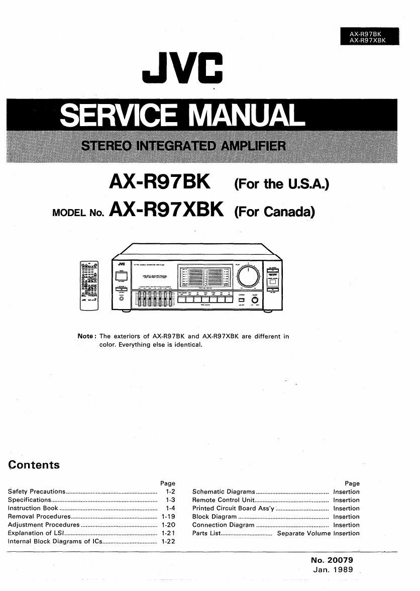
Jvc AXR 97 BK Service Manual
This is the 44 pages manual for Jvc AXR 97 BK Service Manual.
Read or download the pdf for free. If you want to contribute, please upload pdfs to audioservicemanuals.wetransfer.com.
Extracted text from Jvc AXR 97 BK Service Manual (Ocr-read)
Page 1
AX7R97BK I
AX-R97XBK j
JVB
SERVICE MANUAL
AX-R97BK (For the USA.)
MODEL No. AX-R97XBK (For Canada)
E'Q
Note: The exteriorsof AX-R97BK and AX-R97XBK are different in
color. Everything else is identical.
Contents
Page Page
Safety Precautions. . 1-2 Schematic Diagrams... . Insertion
Specifications... 1-3 Remote Control Unit... Insertion
Instruction Book . 1-4 Primed Circuit Board Assy. Insertion
Removal Procedures... . 1-19 Block Diagram .......... Insertion
Adjustment Procedures . 1»20 Connection Diagram Insertion
Explanation of LSl ..................... . 1-21 Parts List ................................ Separate Volume Insertion
Internal Block Diagrams of ICs. . 1-22
No. 20079
Jan. 1989
Page 2
Ax-Re7ek
AX-R97XBK
rSafety Precautions
1. The design of this product contains special hardware and many circuits and components specially for safety purposes.
For continued protection, no changes should be made to the original design unless authorized in writing by the
manufacturer. Replacement parts must be identical to those used in the original circuits. Service should be per-
formed by qualified personnel only.
2. Alterations of the design or circuitry of the product should not be made. Anv design alterations of the product
should not be made. Any design alterations or additions will void the manufacturers warranty and will further
relieve the manufacturer of responsibility for personal iniury or property damage resulting therefrom.
3. Many electrical and mechanical parts in the product have special safety-related characteristics. These characteristics
are often not evident from visual inspection nor can the protection afforded by them necessarily be obtained by
using replacement components rated for higher voltage, wattage, etc. Replacement parts which have these special .
safety characteristics are identified in the Parts List of Service Manual. Electrical components having such features :
are identified by shading on the schematics and by (A) on the Parts List in the Service Manual. The use of a sub-
stitute replacement which does not have the same safety characteristics as the recommended replacement part shown
in the Parts List of Service Manual may create shock, fire, or other hazards. l
4. The leads in the products are routed and dressed with ties, clamps, tubings, barriers and the like to be separated from
live parts, high temperature parts, moving parts and/or sharp edges for the prevention of electric shock and fire hazard.
When service is required, the original lead routing and dress should be observed, and it should be confirmed that they
have been returned to normal, after re-assembling.
5. Leakage current check (Electrical shock hazard testing) ;~-
After re-assembling the product, always perform an isolation check on the exposed metal parts of the product
(antenna terminals, knobs, metal cabinet, screw heads, headphone iack, control shafts, etc.) to be sure the product
is safe to operate without danger of electrical shock.
Do not use a line isolation transformer during this check.
0 Plug the AC line cord directly into the AC outlet. Using a Leakage Current Tester", measure the leakage current
from each exposed metal part of the cabinet, particularly any exposed metal part having a return path to the
chassis, to a known good earth ground. Anv leakage current must not exceed 0.5 mA AC (r.m.s.).
0 Alternate check method
Plug the AC line cord directly into the AC outlet. Use an AC voltmeter having 1,000 ohms per volt or more sensi-
tivity in the following manner. Connect a 1,500 9 10W resistor paralleled by a 0.15 pF AC-type capacitor be-
tween an exposed metal part and a known good earth ground. ;
Measure the AC voltage across the resistor with the AC VOLTMETER
AC voltmeter. @ (Having 1000 ohms/volt.
. . or more sensitivity.)
Move the resrstor connection to each exposed metal
part, particularly any exposed metal part having a
return path to the chassis, and measure the AC volt-
age across the resistor. Now, reverse the plug in the mace this probe _
AC outlet and repeat each measurement. Any voltage on each exposed
measured must not exceed 0.75VAC (r.m.s.). This 150M row metal part.
corresponds to 0.5 mA AC (r.m.s.).
OJSuF AC TYPE
Good earth ground
rWarning
1. This equipment has been designed and manufactured to meet international safety standards.
2. it is the legal responsibility of the repairer to ensure that these safety standards are maintained.
3. Repairs must be made in accordance with the relevant safety standards. ; .
4. It is essential that safety critical components are replaced by approved parts.
5. if mains voltage selector is provided, check setting for local voltage.
1-2 (No. 20079)
Page 9
1 kHz: Most effective in emphasizing or de-emphasizing the
human voice. Emphasize to cause the vocalist to be brought to
the foreground, or tie-emphasize to cause it to recede into the
background.
2.5 kHz: This frequency stimulates the human ear. If the music
sounds hard or metallic, de-emphasize.
6.3 kHz: Boost to add clarity to winds and strings. This he
quency band varies the tonal expression, influencing the sub-
tleties of the music.
16 kHz: Boosting this frequency range properly adds to the
delicacy of highs, with cymbals and triangles resounding in a
more ear»pleasing manner, and provides a feeling of extension.
This frequency band can aiso be used to compensate for car-
tridge response since most moving-magnet cartridges have
their resonance peaks in the frequency range from 10 kHz to
20 kHz.
Q SOURCE SELECTOR
TAPE ZIMONITOR: Press to listen to a cassette deck con-
nected to the TAPE 2 terminals. Press again. and this button
will release this function so that the source selected by another
source select button may be heard.
Note: .
o Press this button to monitor the recorded sound (listening
to the sound just recorded) when using a three-head tape
deck.
TAPE 1: Press to listen to a cassette deck connected to TAPE
1 terminals.
CD: Press this button to listen to a compact disc player con-
nected to the CD terminals.
TUNER: Press this button to listen to a radio broadcast.
PHONO: Press to listen to a turntable connected to the
PHONO terminals.
VCR: Press this button to listen to the sound of the VCFI con-
nected to the VCR terminals.
TV: Press this button to listen to the sound from the TV con-
nected to the TV terminals.
@sounce indicator
The indicator light corresponding to the source selector button
pressed.
0 LOUDNESS
Press this button to compensate for the ears lower sensitivity
at low listening levels.
0 BALANCE
Use to adiust the balance between the left and right speakers.
Normally set this control to the center click position.
How to use the instruction book
When reading the descriptions of items such as the remote control
unit, COMPU LINK system, use the instruction book with the
corresponding illustration page folded open. (See the figure
below.)
OPages with diagrams
Remote control unit ........ . . . . . . . . . . . 13
COMPU LINK system ......................... 14
Remote control unit COMPU LINK system
Text Diagram Diagram Text
we.
5--
9-
na -
AX-R97BK {
AXvR97XBK .
REMOTE CONTROL UNIT
(RM-SA97U)
9 POWER
AUDIO: Press this button to switch the AX-Ft97BK's power on
or off.
TV: For use with the TV. Press this button to switch the TVs
power on or off. ,
VCR: For use with the VCR. Press this button to switch the
power on or off.
Note:
0 Provided one of JVC-specified VCRs or We are used, they
can be remote-controlled.
I Before operating the television or VCR by remote control,
he sure to carefully read the television or VCR instruction
manual.
0 PLAY MODE
Press this button for changeover to CD AUTO CHANGER
CONTINUE: press this button to listen to the compact discs
loaded in the CD magazine in the loaded (numerical) order
regardless of the setting for programmed playback,
PRGM: Press this button to listen to the compact discs in pro-
grammed order.
MAG.PRGM: Press this button to listen to the compact discs
in the order of the program previously stored for each
magazine.
0 co CHANGER
These buttons are for use in specifying a disc or track by its
number. When so speciiying the No. of a particular disc or
track, the 10 KEY buttons 6 must be switched over to serve
the changer in advance.
else: To specify a disc No, press this DISC" button first and
press 10 KEY buttons @( ~ ) corresponding to the
No. 0 button is for use in specifying the disc in PLUS
ONE TRAY when the CD changer has that
TRACK: To specify a track No., press this TRACK button first
and press 10 KEY buttons @( -, 1:] ) cor-
responding to the No,
Notes:
0 For the proper method of using 10 KEY buttons. see page
7.
0 To play a compact disc, press IE buton ill) .
o For details on the CD auto changer, consult its instruction
book.
0 SOURCE CONTROL
FM: Press this button to listen to an FM broadcast
AM: Press this button to listen to an AM broadcast
TV: Press this button to listen to the TV connected to the TV
terminals.
VCR/VIDEO 1: Press to listen to the VCR connected to the
VCR terminals and select the external input VIDEO 1" on the
TV set at the same time.
Notes:
a Where the input to the TV is VIDEO 1 which is connected
to the VCR, a black-and-white stripe pattern will appear on
the TV screen when the VCR is switched to FF, REW or
STOP. The video noise will sometimes affect the systems
audio system as audio noise. When switching to another
source, switch the TV input to a source other than VIDEO
1.
O Consult instruction book of VCR, VIDEO and TV.
(No. 20079)
1-9