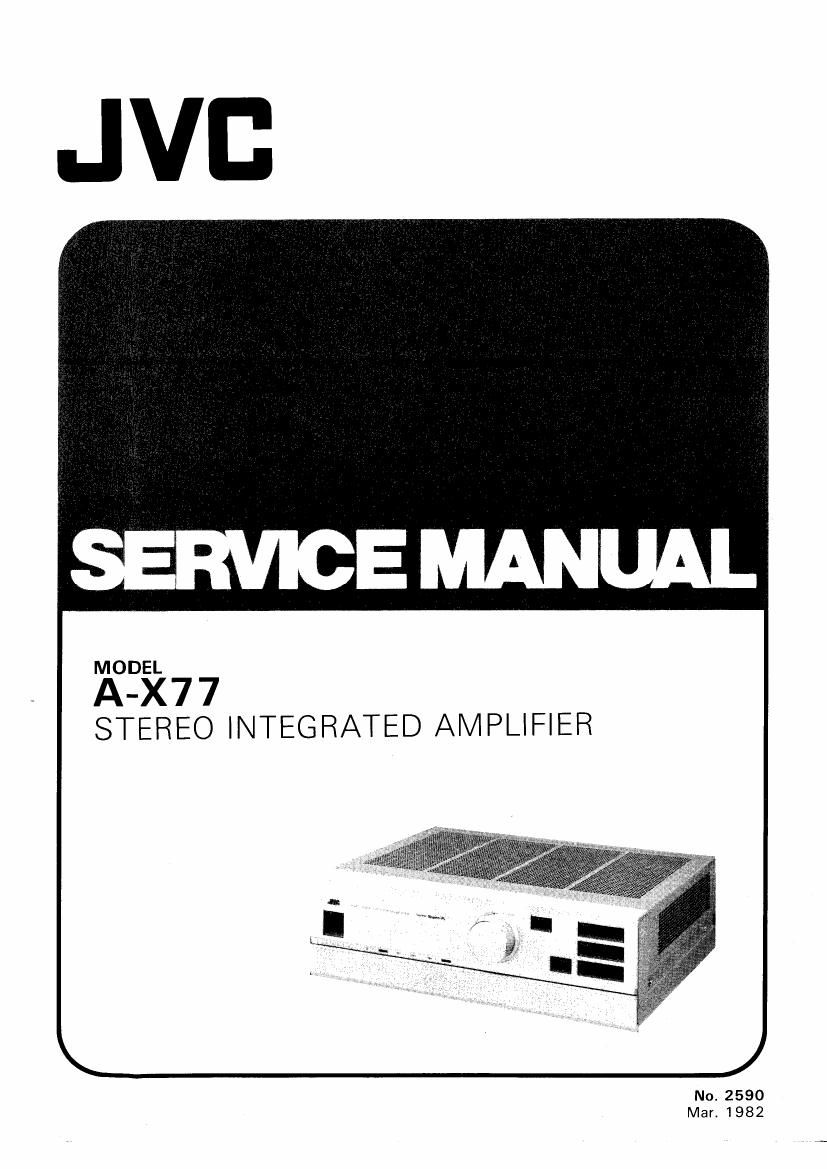
Jvc A X77 Service Manual
This is the 23 pages manual for Jvc A X77 Service Manual.
Read or download the pdf for free. If you want to contribute, please upload pdfs to audioservicemanuals.wetransfer.com.
Extracted text from Jvc A X77 Service Manual (Ocr-read)
Page 1
MODEL
A-X77
STEREO INTEGRATED AMPLIFIER
No. 2590
Mar. 1982
Page 2
Contents
2. Technical Explanation of Dynamic Super-A
3. Main Parts Location and Part Numbers .
61¢th
. Specifications ......................................
2-(1) Basic Configuration of Dynamic Super A
Power Amplifier ..............................
2-(2) Dynamic SuperA" Circuit Operati n .
3-(1) Front View .............................
3-(2) Rear View
3-l3) Top View
. Block Diagram
. Exploded View and Part Numbers
. Amplifier Adjustment procedures ..
611) Drive Amp. Center Voltage Adjustment ..
6-l2) Power Amp. Idling Current Adjustment ..
Warning: When replacing the parts marked with A , be sure
to use the designated parts to ensure safety.
1
. Specifications
CIRCUITRY
Preamplifier : ICL, DC-servo MC/MM
equalizer with EL-FETs in its
initial stage
Power amplifier : 3Stage differential ICL»DC
Dynamic Super»A" power
amplifier with cascade»
connected dual FETs and a
boot strap amp in its initial
stage
ALLOVER CHARACTERISTICS
Output power (AUX IN -- SP. OUT)
1 kHz : 95 watts RMS per channel
min. (8 ohms, 0.0005 % total
harmonic distortion measured
by JVC Audio Analyze System)
: 100 watts RMS per channel
min. (8 ohms. 0.7 /0 total har-
monic distortion)
20 Hz 77 20 kHz : 90 watts RMS per channel
min. (both channels driven into
8 ohms from 20 Hz to 20 kHz
with no more than 0.003 %
total harmonic distortion.)
Total harmonic distortion
AUX IN - SP. OUT : 0.003 % (20 Hz-20 kHz.
8 ohms) at 90 watts
PHONO IN - SP. OUT
at Volume -30 dB : 0.005 % (20 Hz-ZO kHz,
8 ohms) at 90 watts
Intermodulation distortion
(AUX IN - SP. OUT) :0.001 °/a (60 Hz: 7 kHz=4z 1,
8 ohms) at 90 watts
Power band width : 5 H2760 kHz (lHF,0.02 %,
(AUX IN» SP. OUT) 8 ohms both channels driven)
Frequency characteristic : DC-300 kHz +0, e 3 dB
(8 ohms)
Damping factor : 150 (1 kHz, 8 ohms)
Input terminals
A-X77
No. 2590
|nput sensitivity/impedance (1 kHz)
PHONO (MM) : 2.5 mV/47 kohms
PHONO (MC) : 200 )LV/10o ohms
TUNER : 200 mV/47 kohms
AUX : 200 mV/47 kohms
TAPE : 200 mV/47 kohms
Page
7. Printed Circuit Board Ass'y and Parts List ........ 9 ~ 18
7-(1) TXX-372 Equalizer Amp.
P.C. Board Assy ................................ 9 ~- 11
7-(2) TXX-373 Drive Amp.
P.C. Board Assy .............................. 12 ~ 14
7-(3) TXX-374 Power Amp.
P.C. Board Assy... . 15~18
.. 18
.. 18
.18
19
..19
.20
.21
7-(4) TPS-287C AC Unit P.C. Board Ass y.
7-(5) TPS-287D AC Unit P.C. Board Ass'y
7-(6) TPs-287E AC Unit P.C. Board Ass'y.
8. Packing Materials and Part Numbers .
9 Accessories List .
10. A-X77 Schematic Diagram
1 1. Power Supply Block for Designated Areas ..
12. Parts List with Specified Numbers
for Designated Areas ....................................... 22
Signal-to-noise ratio
PHONO (MM) : 86 dB
PHONO (MC) : 72 dB (250 ,lv input)
TUNER : 1 10 dB
AUX : 1 10 dB
TAPE : 1 10 dB
(IHF A Network short circuit)
PHONO (MM) : 83 dB (Flec out)
PHONO (MC) : 76 dB (Rec out)
TUNER : 84 dB (Speaker out)
AUX : 84 dB (Speaker out)
TAPE : 84 dB (Speaker out)
(IHF A7202)
Tone controls : TREBLE: £8 dB (10 kHz)
BASS: :8 dB (100 Hz)
Subsonic filter : 18 Hz (-6 dB/oct)
Loudness control : 100 sz+ 6 dB,1O kHz:+ 4 dB
(at VOLUME ~30 dB)
Muting level : -20 dB
EQUALIZER
PHONO overload capacity
PHONO (MM) : 300 mV (1 kHz, 0.0008 %
THD)
PHONO (MC) : 23 mV (1 kHz, 0.001 % THD)
PHONO RIAA deviation : i0.2 dB (20 H1720 kHz)
Total harmonic distortion
PHONO (MM) : 0.002 "/0 (at 8 V output,
20 HZAZO kHZ)
PHONO (MC) : 0005 % (at 8 V output,
20 H2720 kHz)
Recording output
Output level/impedance
TAPE REC : 200 mV/660 ohms (PHONO)
GENERAL
Power source : See page 22
Dimensions :5-1/2(H)x17-1/8"(W)x
1577/8(D)
(14,0 cm(H) x 43.5 cm(W) x
40.2 cm(D))
Weight : 24.2 lbs. (11.0 kg)
De5ign and specificatlons subject to change Wlthoul notice.