Jvc A M1 Schematic

This is the 6 pages manual for Jvc A M1 Schematic.
Read or download the pdf for free. If you want to contribute, please upload pdfs to audioservicemanuals.wetransfer.com.

Page: 1 / 6
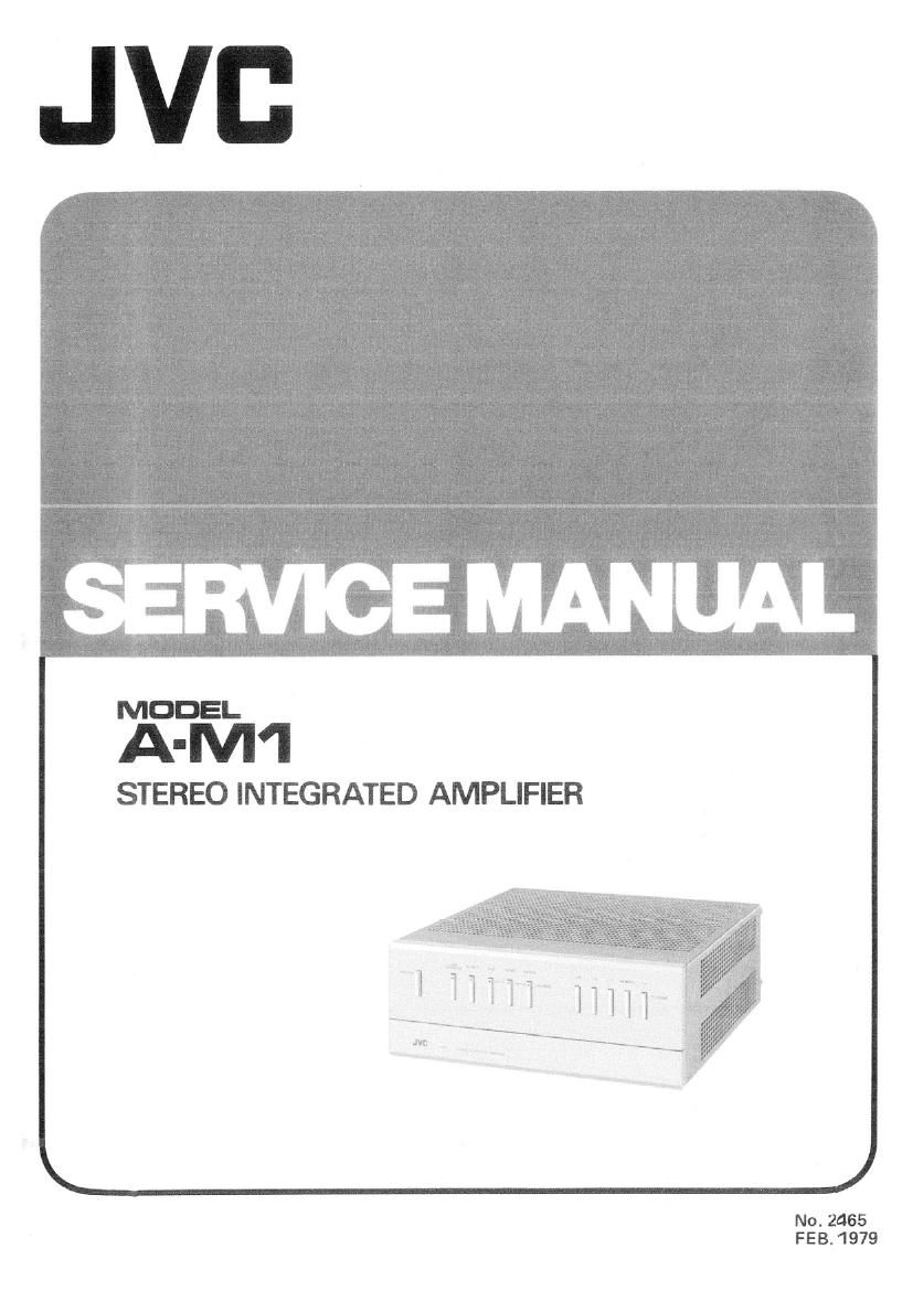
Jvc A M1 Schematic

Extracted text from Jvc A M1 Schematic (Ocr-read)


Page 1

Kim

STEREO INTEGRATED AMPLIFIER

N0. 2465
FEB. 1979

Page 2

Contents

Page
1. Specifications ................................................................ 1
2. Technology of Digital Power Supply (for USA)
2-(1) Block Diagram ..... . ................................................... 2
2-(2) Trigger instant Start Circuit ................................................ 2
2(3) Inverter Circuit ........................................................ 3
3. Adjustment Procedures
3-) Digital Power Supply (for USA) .............................................. 4
3-(2) Power Amplifier ........................................................ 5
4. Removal Procedures
4-(1) Cabinet .............................................................. 5
4-(2) Front Panel and Chassis ................................................... 5
MS) Rear Panel ................................................ . . . . . ....... 5
4(4) From Bracket . . ....................................................... 6
4-(5) Knobs .............................................................. 6
4-(6) Headphones 8: Speaker Switch (TSC-121B) P. C. Board Assy .......................... 6
4-(7) Loudness Switch P. C. Board Ass'y ........................................... 6
4(8) Volume Bracket . . ...................................................... 6
4-(9) Power Switch .......................................................... 6
4-(10) Heatsink and Driver Amp. (TXX-165-1) P.C. Board Ass'y ............................. 6
4(11) Equalizer Amp. (TXX-1633) 81 Electronics Switch (TXX-1SZB) P.C. Board Ass'y ............ 7
4-( 12) Protector Circuit (TXX-165-2) P.C. Board Ass'y ................................... 7
4-(13) Digital Power Supply (TDC31C) P.C. Board Ass'y (for USA). . .......... . ...... - ........ 7
4414) Fuse (F801) (for USA) .................................................... 8
4(15) Toroidal Transformer Power Supply (TXX-203A) P.C. Board Ass'y ...................... 8
4-(16) Fuse (F801, F802, F803) .................................................. 8
5. Main Parts Location
5(1) Equipped with Digital Power Supply . . . . ...................................... 9
5(2) Equipped with Toroidal Transformer Power Supply ................................ 9
6. Exploded Views and Part Numbers
6(1) Front Panel ........................................................... 10
6-(2) Power IC: .......................................................... . . 10
6(3) Power Supply Section ....... . ............................................ 11
6-(4) Rear Panel Section ............... . ...................................... 12
7. Primed Circuit Board Ass'y and Parts List
7-(1) TDC-31 Digital Power Supply P.C. Board Ass'y ................................ 13
7-(2) TDC-32 Trigger Instant Stan P.C. Board Assy ................................. 14
7-(3) TSC-1Z1 Headphones & Speaker Switch P.C. Board Ass'y . . ........................ 14
7(4) TXX-161 AC Outlets, Rectifiers & Terminals P.C. Board Ass'y ....................... 14
7(5) TXX-162 Electronic Switch 81 Pin Jacks P.C. Board Ass'y .......................... 15
7(6) TXX-163 Equalizer Amp. & Pin Jacks P.C. Board Assy ............................ 16
7(7) TXX-164 Tone Controls, LEDs & Muting Switch P.C. Board Ass'y . . . . . ............... 18
7(8) TXX-165 Driver Amp. & Protector Circuit P.C. Board Assy ......................... 19
7(9) TXX-166 Power IC's P.C. Board Ass'y ....................................... 20
7~(10) TXX-203A Voltage Selector, Rectifiers & Terminals P.C. Board Ass'y .................... 24
8. Accessories List ........................... . .............. . ..................... 24
9. A-Ml Schematic Diagram ....................................................... 22, 23
10. Packing Materials and Part Numbers .............................................. Back page
11. Parts List with Specified Numbers for Designated Areas ................................ Back page
Warning: When replacing the parts marked with A , be sure to use the designated parts to ensure safety.
1 . Specrflcation
Output power : 50 Watts per channel, min. RMS, RIAA PH equalization : :03 dB (20 Hz - 20 kHz)
both channels driven, intoB ohms, Input sensitivity : PHONO 2.5 mV (47 k ohms)
from 20 Hz to 20 kHz with no (Impedance) TUNER. AUX. TAPE PLAY
more than 0.03 % total harmonic 150 mV (47 k ohms)
distortion Dimensions : 93 x 230 x 269 (mm)
Load impedance : SYSTEM 1 or2 41-160th (H xWxD) 3-11/16x9-1/16xlOe9/16(inches)

Frequency response : TUNER, AUX, TAPE
DC - 70 kHz :9 dB

FEB. 1979
No. 2465 -1 _