ITT SR 80 Owners Manual

This is the 9 pages manual for ITT SR 80 Owners Manual.
Read or download the pdf for free. If you want to contribute, please upload pdfs to audioservicemanuals.wetransfer.com.

Page: 1 / 9
ITT SR 80 Owners Manual

Extracted text from ITT SR 80 Owners Manual (Ocr-read)


Page 1

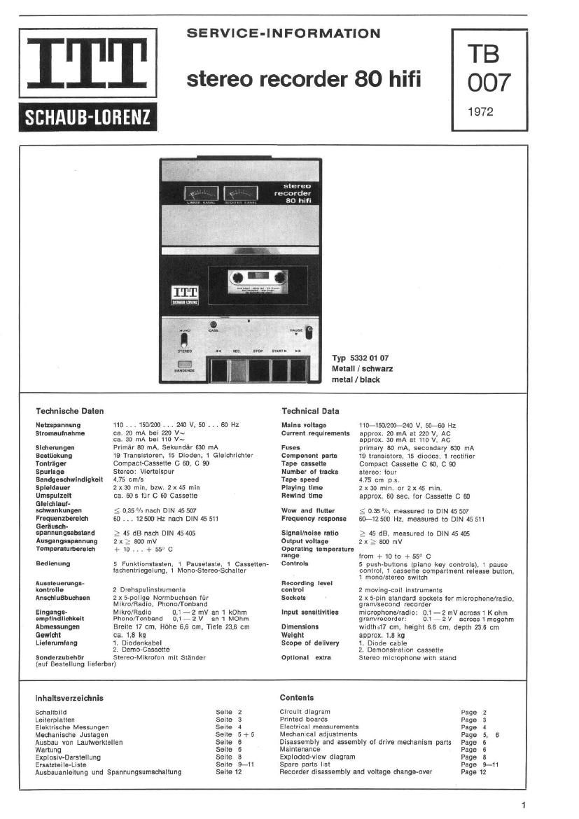
ITT TB
stereo recorder 80 hifi 007

1 972

SERVICE-INFORMATION

516-: reo
recorder
80 hifi

3cm:- mm:

Typ 5332 01 07

Metall / schwarz
metai / black
Technische Daten Technical Data
Netzaplnnung 110 . , . 150/200 . . . 240 V. 50 . . . 60 HZ Mains voltage 110-150/200-240 V. 50-60 Hz
stromautnahme ca. 20 mA bei 220 V~ current requirements approx. 20 mA at 220 V, Ac
ca. 30 mA bei 110 V~ approx. 30 mA at 110 V. AC
Sldierungan Primér 30 mA. Sekundar 630 mA Fuses primary 80 mA. secondary 630 mA
Bustlickung 19 Transistoren. 15 Dioden. 1 Gleichrichter Component part: 19 transistors. 15 diodes, 1 rcctilicr
Tontrttger Compact-Cassette C 60, C 90 Tape cassette Compact Cassette 0 60, C 90
Snurlage Stereo: Viertelspur Number 01 tracks stereo- tour
Bundgewhwlndlgkelt 4.75 cm/s Tape speed 475 cm 9,5.
Spleldauer 2x 30 min. bzw. 2 x 45 min Playing time 2 x 30 min. or 2x 45 min.
Umlpullalt ca. 605 filr C 60 Cassette Rewind time approx. 60 sec. lor Cassette C 60
Glelctilaul-
setmlnkungon < 0,35 /u nach DIN 45 507 Wow and flutter g; 0.35 n/ii, measured to DIN 45 507
Frequenzbereloh so .. . 12500 Hz nach DIN 45 511 Frequency response 60-12500 Hz. measured to DIN 45 511
Gerttuach-
spannungubsund 2 45 dB nach DIN 45 405 Signal/noise ratio :3 45 dB, measured to DIN 45 405
Ausgangsspannung 2x > Boo mV Output "0! 2X E 300 mV
Temperaturberaleh + 10 . . , + 55v 0 Operallng ternPerMure
range lrorn + 10 to + 55° C
Badlmung 5 Funktionstasten. 1 Pausetsste. 1 Cassetten- Control: 5 pushmulzons (piano key controls}. 1 Pause
tachentriegelung, 1 Mono-stereo-Schalter control. 1 cassette compartment release button,
1 mono/stereo switch
Auastouerungn- Recording level
kontrolle 2 D'ehspulinstrumente control 2 moving-coil instruments
Anechluflbucluen 2 x 5-polige Normbuchsen liir Socket: 2 x 5-pin standard sockets tor microphone/radio.
Mikro/Radio. Phono/Tonband gram/second recorder
Elngangn- Mlkro/Radio 0, - 2 mV an 1 kOhm Input aensltivltles microphone/radio: 0.1 - 2 mV across 1 K ohm
empllndllehkolt Phono/Tonband 0.17 2 V an 1 MOhrn gram/recorder: 0.1 7 2 V across 1 megohm
Abmenungen Breite 17 cm. Hfiha 6.6 cm. Tielo 23,6 cm Dimensions width-.17 cm. height 6.6 cm, depth 23.6 cm
Gwloht ca. 1.8 kg Weight approx. 1.8 kg
Listemmtang 1. Diodenkabel Scope of dellvery 1. Diode cable
2. Demo-Cassette 2, Demonstration cassette
Sonderzubehbr Steteo-Mlkroton mlt stander Optional extra Stereo microphone With stand

(aut Bestellung Iielerbar)

lnhaltsverzelctmls Contents

Schaltbtid Seite 2 Ctrcult diagram Page 2
Leiterplatten Seite 3 Printed boards Page 3
Elaktrische Messunger Seite 4 Electrical measurements p.99 4
Medianische Justagen Seite 5+6 Mechancal adiustments Page 5, 6
Ausbau von Laulwerkteilen Seite 6 Disassembly and assembly of drive mechanism parts Page 6
Wartung Seite 6 Maintenance Page 5
ExplosiwDarstellung Seite 8 Exploded-view diagram Page 3
Ersatzteile-Liste Sane 9-11 Spare parts Lst page 9_11

Ausbauanleitung und Spannungsumsohaltung Seite 12 Recorder disassembly and voltage change-over Page 12

Page 2

Reparaturhinweise - Repairing Hints

FlG.A FIG. B

lo
I

Ullllll

FIG. C

c252 eflmA

1. Abnahme des Gehfiuseohertells (Fig. A)

a) Am Gehttuseooden die 4 versenkten Sd'trauben ® an den Eaten
der abgesohragten Gehfiusekanten herausdrehen.

b) Falls das Chassis eusgebaut warden soil, die 2 Gummlstopien ®
aua den Lochern entternen und die darunter betindlichen Sohrauben
hereusdrehen (siaha Absatz 3. unten).

c) Des Gerat vorsiohtig umdrehen. Tonto CASS. aualboon; do- Go-
hiucoobortoll dart nur mit geottnetem Callahan-Halter abgenomman
wardenl

d) Gehéuseobeneil vorsichtig anheben und urn 180° neon links klppen.

2. Gehiuseelnbau

Beim Einbau dos Gehauseoberteiles daraut achten. dafl die Cassetten-
andruckfeder niont verbogen wlrd und kaine Verbindungsleitungen
eingeklemmt werden.

3. Chassisausbau (Fig. B)

a) Absohnitte a). b). c) und (1) von Abaatz 1. ausiiihren.

b) Die zwei Schrauben ® und die zwel Sohrauben © an der Oberseite
des Chassis herausdrehen.

c) Chassis vorsiohtig anheben und urn 90a nadt links kippen. Gehéuse-
untenall und chassis weiterkippen. his das Chassis tlach aut dem
Geniuseobertell Iiegt. Wehrend des Kippens aut die Verbindungs-
leitungen und den Verriegelungshaken © tiir den Cassettandeokel
aontenl

4. Chasslseinbau

Der chassieeinbau ariolgt sinngeméii in umgekehrter Fteiheniolge von
Absohnitt 3. und 2. Kaine Verbindungsieitungen einklemmen.

5. Spannungsumachaitung (Fig. B und C)
(Im Werk wurde das Geriit auf 200 240 V-Betriab eingestellt)

a) Zur Umschaltung aut 110 150 V-Betrieb zuerst Gehéiuseoberteil
abnehmen (siehe Absatz 1. a). c). d).

h) Die 2 Schrauben ® harausdrehen und das Abdeckplattdten ® iiber
der wmA-Sicherung abnehmen.

c) Naoh Abnahme der Isolierungen den Verbindungspunkt ® der
Dréhte arr und we trennen und elne neue Verbindung zwisctten den
Drahten lw und bl herstellen und wieder abisolieren.

d) Dia Buchsenabdackplatte an der Riickseite des Gerétes nach
oben herausziehen und wieder so elnstadten. daB die Beschrittung
110-150 V ~ zu lesen ist.

DECIDE

2 2m

1. To remove top at case (Fig. A)

a) Unscrew the four countersunk screws (D irom the corners oi the
sloping bottom edges.

b) It it is intended to dismantle the chassis, remove the two rubber
plugs Q) from the holes and unscrew the screws located under-
neath the holes. (See section 3. below).

c) Ceretully turn the set around, Role-u tho CASS. button; take
all the top at the can only when the cluatto holder I: open.

d) carefully litt top of case and tilt it by 150° to the left.

2. To replace top at case

When reinstalling top at case. make sure that the cassette pressure
spring is not twisted and that the leads are not trapped.

3. Chassis removal (Fig. 3)

a) Periorm the steps of sections a), b). c) and d) oi paragraph 1.

b) Unscrew the two screws ® and the two screws (9 trom the upper
side of the chassis.

c) Caretully liit the chassis and tilt it by 90° to the left. Tilt the
lower part oi the case and the chassis until the chassis lies list
on the top of the case. While tilting the base and chassis. take
care that the leads are not trapped and the latch hook @ tor the
cassette lid is not deformed.

4. To replace the chassis assembly

To reinstall the chassis, reverse the procedure outlined in the sections
a. and 2., taking care not to trap the leads.

5. Voltage changeover (Figs. B and C)
(The recorder was adjusted at the iactory tor 200-240 V operation)

a) To change over to 110-150 V operation. remove top of case (see
section 1. a). c). d).

b) Unscrew the two screws @ and remove the small plate ® covering
the 80 mA (use.

c) Alter removing the insulation, disconnect the sw and "we" wires
at the point @, establish a new connection between the sw and
bi wires and Insulate them again.

d) Pull out the plate © covering the rear sockets and reinsert it so
that the lettering "110-150 V shows.

0011 8977 (0272)

Bol Roper-tutor! die VDE-Butlmmungen new H Madmen.

Anderungen vorbehalten - Modifications reserved