Heathkit ID 5001 Instructions Manual

This is the 4 pages manual for Heathkit ID 5001 Instructions Manual.
Read or download the pdf for free. If you want to contribute, please upload pdfs to audioservicemanuals.wetransfer.com.

Page: 1 / 4
Heathkit ID 5001 Instructions Manual

Extracted text from Heathkit ID 5001 Instructions Manual (Ocr-read)


Page 1

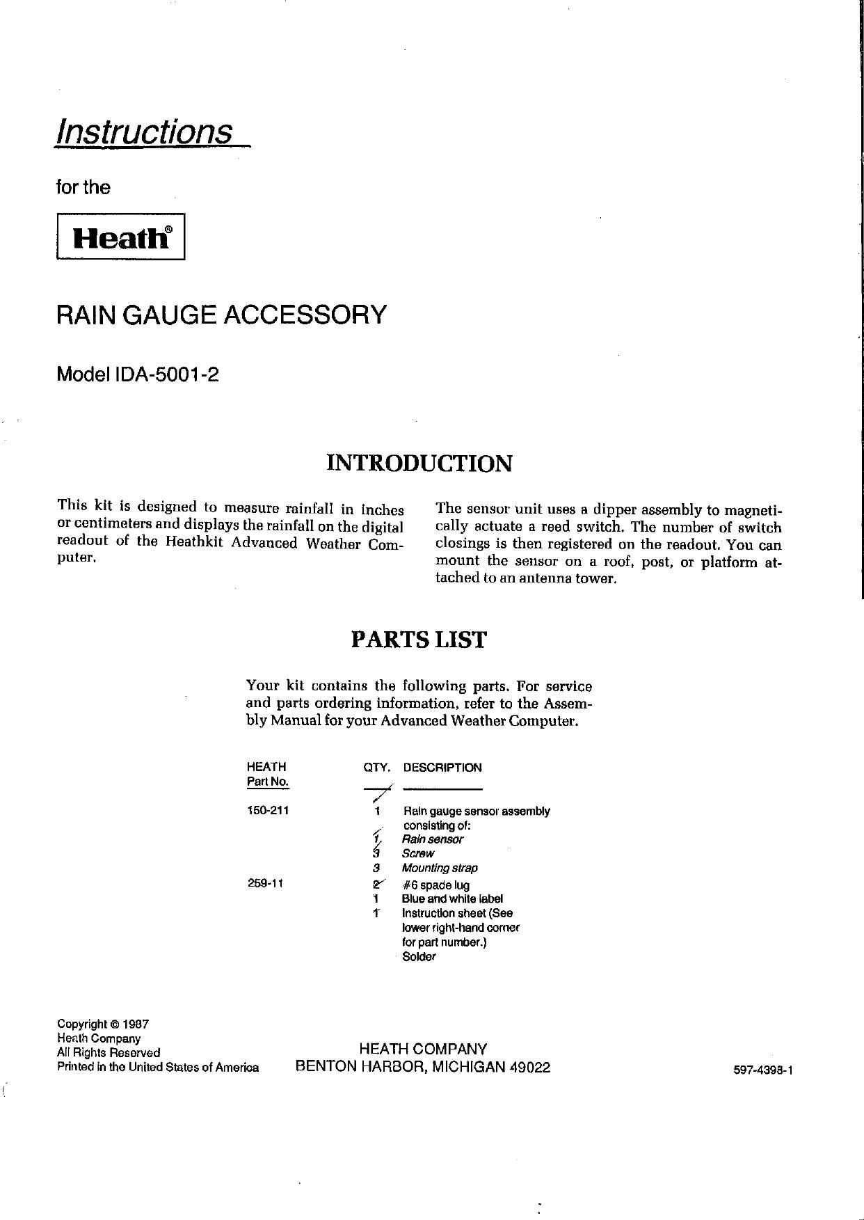
Instructions

for the

Heatfl"

RAIN GAUGE ACCESSORY

Model IDA-5001-2

This kit is designed to measure rainfall in inches
or centimeters and displays the rainfall on the digital
readout of the Heathkit Advanced Weather Com-

puter.

Copyright © 1987
Heath Company
All Rights Reserved

INTRODUCTION

The sensor unit uses a dipper assembly to magneti-

cally actuate a reed switch. The number of switch

closings is then registered on the readout. You can

mount the sensor on a roof, post, or platform at-

tached to an antenna tower.

PARTS LIST

Your kit contains the following parts. For service
and parts ordering information, refer to the Assem-
bly Manual for your Advanced Weather Computer.

HEATH

Part No.

150-211

259-11

Printed in the United States of America

QTY. DESCRIPTION
1 Reln gauge sensor assembly
/, oonslstlng ol:
9 Fla/n sensor
3 Screw
3 Mounting strap
2 #6 spade lug
'1 Blue and whlte label
1 Instruction sheet (See
lower right-hand corner
for part number.)
Solder
HEATH COM PANY

BENTON HARBOR, MICHIGAN 49022

597-4398- 1

Page 2

Page 2

PREPARATION AND CALIBRATION

RAIN SENSOR PREPARATION
Refer to Pictorial 1 for the following steps.

WARNING: The collector ring is made of thin metal
and can have very sharp edges. Handle the sensor
carefully to avoid cuts.

[ ) Carefully remove the sensor [#150-211) from
its shipping carton.

[ ] Separate the sensor wires for 3/4" and remove
1/ of insulation from each wire end. Then
twist the bare wire ends and add a small
amount of solder to hold the wire strands to-
gether.

[ ) Refer to the inset drawing in Pictorial 1 and
- grasp the sensor at its narrowest point; then
carefully pry the base off with your fingertips.

NOTE: The sensors movable dipper is coated with
a white film that prevents water from collecting on
its surface. Do not touch or remove this film from
the dipper, as it will cause a calibration error.

[ ) Remove any packing materials which prevent
the dipper from moving.

Connect either sensor wire to the Weather Com-
puters terminal strip labeled RAIN as follows:

( ) Either wire to lug 3.
( ) Other wire to lug 4.

[ ) Carefully rock the sensor dipper from one side
to the other. You should hear a click from the
sensor each time the sensor moves to the oppo-
site stop, and the display should increment by
.01 for inches or .0254 for centimeters

NOTE: The sensor has been accurately calibrated,
and does not require additional calibration.

If the sensor increments properly, proceed to "Instal-
lation." If the sensor does not increment properly,
perform the following steps.

[ ) Examine the dipper assembly. The short dip-
per leg should be against the small head on
the dipper shaft, and the long leg (with the
magnet attached] should be against the adjust-
ment screw at the opposite end of the shaft:
The magnet should be about 1/16" away from
the glass tube containing the contacts.

[ ) Rock the dipper from stop to stop If you hear
no click, or a click only when the dipper
moves in one direction, carefully reposition
the glass tube to center the contacts in the mag-
nets path. Then recheck the dipper operation.

If the contacts still do not close properly:

1. Loosen the nylon nut on the bead side of the
shaft and turn the adjusting screw 1/4-turn
counterclockwise. Then retighten the nut.

2. Loosen the nut on the opposite end of the
shaft, turn the adjusting screw 1/4-turn clock-
wise, and retighten the nut.

You should now hear a click when the dipper moves
in either direction, and the readout should incre-
ment properly. If it does not, repeat the above two
steps, repositioning the magnet closer to the con-
tacts. The magnet should not end up closer than
1/16 to the glass tube. Then complete the following
step and proceed to Installation.

[ ) Disconnect the sensor wires from the Weather
Computer.

[ ) Remove the backing paper from the blue and
white label. Then press the label into place
next to the existing labelsfs) on the bottom of
the Weather Computer chassis.

Heathkif

Heathkit

Page 3


FRY OFF BASE
WITH FINGERS

SENSOR WIFIES

CALIBRATION
ADJUSTMENT

MAGNET
\\\\
ADJUSTING SCREW SCREW

NYLON NUT
pusn on PULL T0

GLAS T

BEAD s BE CENTER GLASS TUBE

PICTORIAL 1

CALIBRATION ADJUSTMENT