Heathkit HWA 7 1 Schematic

This is the 1 pages manual for Heathkit HWA 7 1 Schematic.
Read or download the pdf for free. If you want to contribute, please upload pdfs to audioservicemanuals.wetransfer.com.

Page: 1 / 1
Heathkit HWA 7 1 Schematic

Extracted text from Heathkit HWA 7 1 Schematic (Ocr-read)


Page 1

CIRCUIT DESCRIPTION

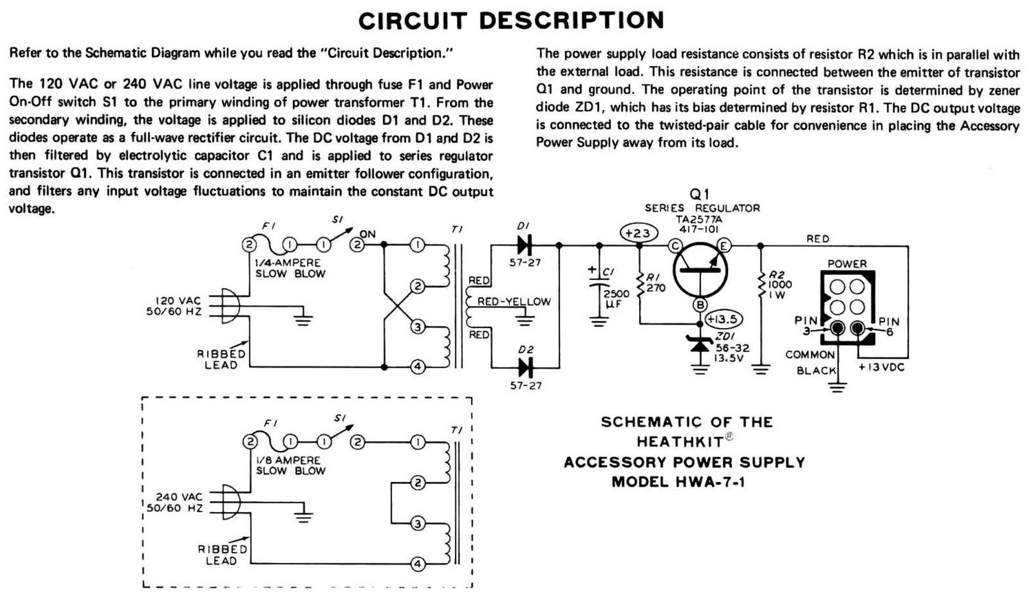
Refer to the Schematic Diagram while you read the "Circuit Description."

The 120 VAC or 240 VAC line voltage is applied through fuse F1 and Power
On-Off switch 81 to the primary winding of power transformer T1. From the
secondary winding, the voltage is applied to silicon diodes Di and D2. These
diodes operate as a full-wave rectifier circuit. The DC voltage from 01 and DZ is
then filtered by electrolytic capacitor C1 and is applied to series regulator
transistor 01. This transistor is connected in an emitter follower configuration,

The power supply load resistance consists of resistor R2 which is in parallel with
the external load. This resistance is connected between the emitter of transistor
01 and ground. The operating point of the transistor is determined by zener
diode 201, which has its bias determined by resistor Rl. The DC output voltage
is connected to the twisted-pair cable for convenience in placing the Accessory
Power Supply away from its load.


and filters any input voltage fluctuations to maintain the constant DC output Q1
voltage. SERiES REGULATOR
5/ TA2577A
F/ N 7-, D/
We O H 1 5°
l/4~AMPERE 57-27 + Cl POWER
SLOW BLOW 2
RED :: new 0 O
\ 2500 IW
$32;ch _ RED~YELLOW up 0 O
5 j l: = 1- PIN PIN
RED 20/ 3
j 02 55-32
maeso ,3. COMMON
LEAD 4 = = BLACK +l3VDC
57-27 =
r- ----------------------- -
Fl 5 n SCHEMATIC OF THE
W HEATHKlTa'

I/a AMPERE
SLOW BLOW ACCESSORY POWER SUPPLY

l
I I
|
: l
| I
l

I

l '\ '
240 VAC _ l
50/60 HZ I
' I
I l
I I
I I
I I
l

A I
\4/

MODEL HWA-7-1