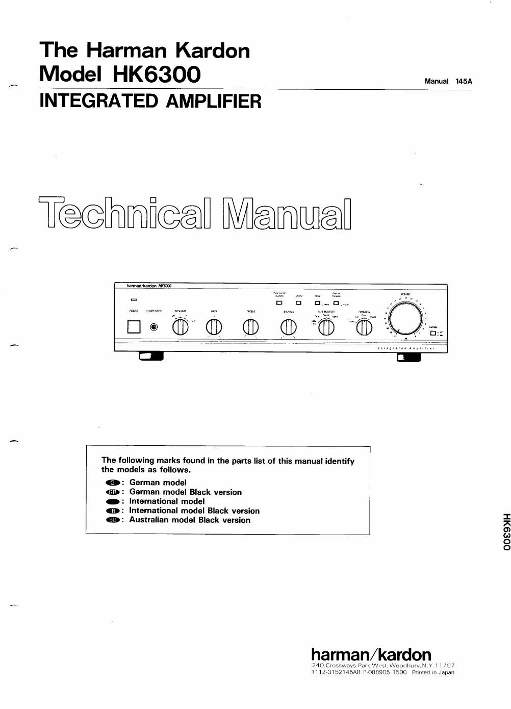
Harman kardon hk 6300 service manual
This is the 24 pages manual for harman kardon hk 6300 service manual.
Read or download the pdf for free. If you want to contribute, please upload pdfs to audioservicemanuals.wetransfer.com.
Extracted text from harman kardon hk 6300 service manual (Ocr-read)
Page 1
The Harman Kardon
Model HK6300
INTEGRATED AMPLIFIER
Teflmficeafl Manual
The following marks found in the parts list of this manual identify
the models as follows.
: German model
: German model Black version
: International model
: International model Black version
: Australian model Black version
966%
harman/kardon
240 Crosswavs Park Wesl,WOx)tihur\/.N Y 1 l 197
HiZ-3152145A8 P7088905 1500 Prunerl In Japan
OOSSMH
Page 2
HK6300
SPECIFICATIONS
Nominal Limit
RMS Output Power
89, 20Hz~20kHz THD 0.09% 70.8W§60W
4Q, 1kHz THD 0.3% 72.2W260W
High Instantaneous Current
Capability (HICC) 40A :35A
Half Power Bandwith 10Hz~100kHz
Frequency Responce at - 3dB O.62Hz~136kHz*
Input Sensitivity
Tuner 135mV325mV
Phono(MM) 2.4mV:0.2mV*
Phono(MC) 150uV i 20pV *
Signal to Noise Ratio
Tuner 82:18; 75dB
Phono(MM) 79dB g 73dB
Phono(MC) 75.5ng70dB
Channel Separation at 10kHz
Tuner 55dB g45dB
PhonoIMM) 63ng45dB
PhonolMC) 60ng43dB
IM Distortion Ratio 0.048% §O.I %
Damping Factor at 1kHz 66; 50
Tone Control Characteristics
Bass Turnover Frequency (200Hz/400Hz)
Bass at 50Hz/100Hz
Boost 10:18 1 2dB
Cut 10dB : 2dB
Treble Turnover Frequency (2kHz/6kHz)
Treble at 10kH2/30kHz
Boost IOdBi 2dB
Cut 10:18: 2dB
POWER CORD REPLACEMENT
Nominal Limit
Filters
Subsonic 15Hz, - 3dBi1dB/Octave
High Cut 6kHz, - 3dBi1dB/Octave
DC Output Voltage
L channel OmV 1 60mV
R channel OmV: BOmV
RIAA Equalization at Tape Out
(20Hz/20kHz) (No load)
Phono Over Load (No load)
Phono (MM) 143mV g110mV
Phono (MC) 8.0ng5mV
Dimensions (W x H x D) 17-1/2 x 4-1/16 x13-7/8"
(443 x 103 x 351mm)
Weight 17lbs. lOoz. (8kg)
Power SuppIy AC 220/240V, 50/60Hz
Power Consumption 176W
0.18dB +1.0dB/0,18dB - 0.2dB
0.62Hz~180kHz
International model
* Input Sensitivity for International model are 2.2mV
i0.2mV (MM) and 120uVi20uV (MC).
These specifications are service target specs.
Specifications and components subject to change without notice. Overall
performance will be maintained or improved.
In order to prevent fire or shock hazard when replacing the power cord, follow the procedure below to replace the parts
with the standard supply parts.
CABINET BACK
P1
HOLDER
Finch the power cord with
the holder and fit the
holder into the hole on
the cabinet back.
to fix.
BROWN
LEAD
BLUE LEAD
Pass the lead wires
through the holder
1. Twist the lead wire (red) of the Power SW P.C.
Board (PCB-7) and the lead wire (blue) of the
power cord together, and put the connector on
the wires and squeeze with a wrench (JST
YS-1G14).
2. Cover the lead wires with the heat shrinkable
tube in advance and perform heat treatment
after connecting.
CO1
CONNECTOR
POWER SWITCH
PC. BOARD