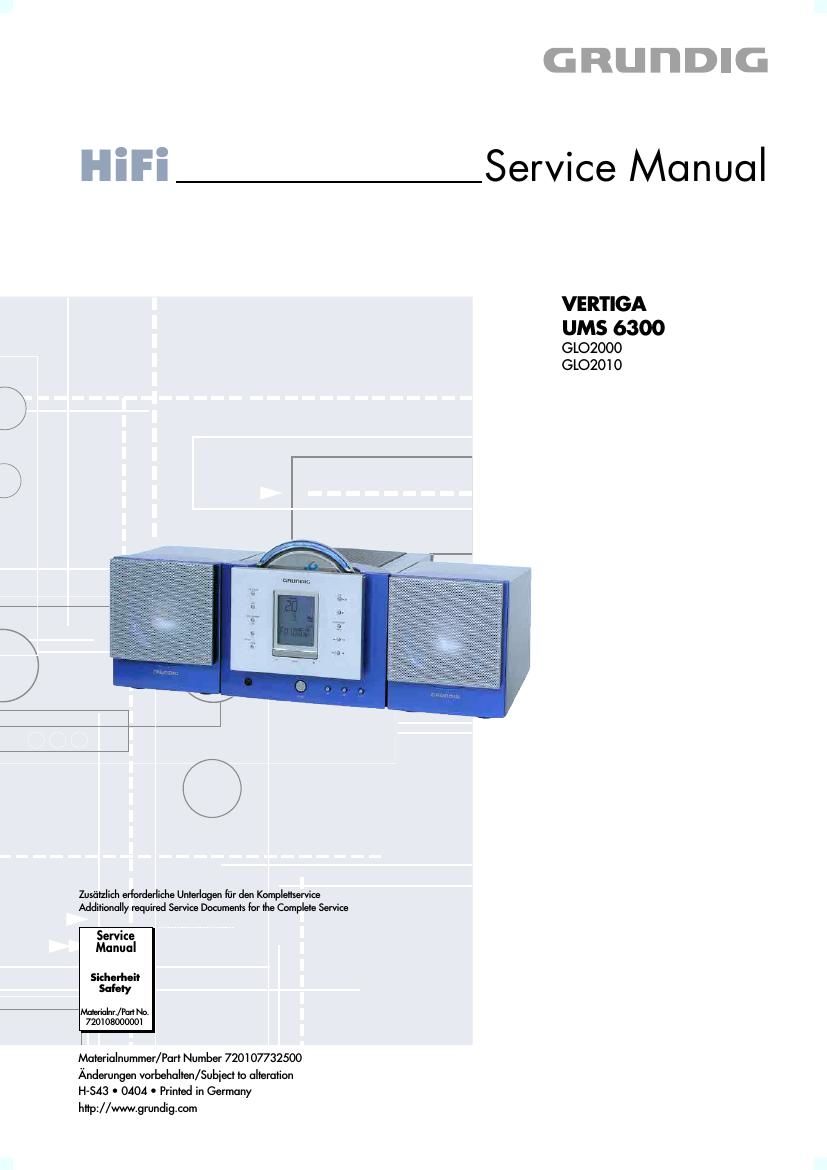
Grundig VERTIGA UMS 6300 Service Manual
This is the 33 pages manual for Grundig VERTIGA UMS 6300 Service Manual.
Read or download the pdf for free. If you want to contribute, please upload pdfs to audioservicemanuals.wetransfer.com.
Extracted text from Grundig VERTIGA UMS 6300 Service Manual (Ocr-read)
Page 1
film .4 m o;
Zusfitzlich erlorderliclie Unterlagen liir clen Kompleflservioe
Additionally required Service Documents for the Complete Service
Service
Manual
Sizherheit
Safety
MalaialnL/Pm No.
7201 08000001
l
Materialnummer/Part Number 720107732500
Anderungen vorbelialten/Subiect to alteration
H-SA3 0 0404 0 Printed in Germany
hflp://www.grundi9.com
GRUI'IDIG
Service Manual
VERTIGA
UMS 6300
GLO2000
GLO2010
Page 2
GRUNDIG Service
VERTIGA UMS 6300
Es gelten die Vorschriften und Sicherheitshin-
weise gemaB dem Service Manual "Sicherheit",
Materialnummer 720108000001, sowie zusatz-
lich die eventuell abweichenden, landes-
spezifischen Vorschriften!
The regulations and safety instructions shall be
valid as provided by the "Safety" Service Manual,
part number 720108000001, as well as the re»
spective national deviations!
lnhaltsverzeichnis
Allgemeiner Teil ............................. 1 - 21 - 7
Messgerate / Messmittel ..
Technische Daten .
Servicehinweise
Ausbauhinweise ..
Bedienhinwelse
Abgleichvorschriften .................................. 2 - 1
Schaltpléne
und Platinenabbildungen ............ 3 - 1 3 - 17
Blockschaltplan .....
Verdrahtungsplan ..
Schaltpléne:
Netzteil
Verstarker-Platte
MCU-Platte...
Kopfhdrer-Platte
Bedien-Platte.
CD-Fach-Position-Sensoren
Display-Platte
Tuner-Platte ..
Platinenabbildunge
Netzteil
Verstarker-Platte
MCU-Platte...
Kopfhdrer-Platte
Bedien-Platte .....
CD-Fach-Position-Sensoren
Display-Platte
Tuner-Platte ..
Explosionszeichnung und
Ersatzteilliste .................................. 4 - 1 4 - 4
Allgemeiner Teil
Messgerate/ Messmittel
Wobbelsender
Digitalvoltmeter
Mess-Sender
Oszilloskop
Klirrtaktormessgerat
Table of Contents
General Section ............................ 1 - 2 1 -10
Measuring Instruments / Equipment .
Technical Data
Service Hints ..
Disassembly Hints ..
Operating Hints
Adjustment Procedures .............................. 2 - 2
Circuit Diagrams
and Layout of PCBs ..................... 3-1 3-17
Block Diagram
Wiring Diagram .
Circuit Diagram
Power Supply
Amplifier Board
MCU Board
Headphone Board
Operation Board
CD Compartment Position Sensors
Display Board
Tuner Board ..
Layout of the PCB
Power Supply 3 - 3
Amplifier Board ..
MCU Board
Headphone Board
Operation Board
CD Compartment Position Sensors
Display Board
Tuner Board ..
Exploded View and
Spare Parts List .............................. 4 - 1 4 - 4
General Section
Measuring Instruments / Equipment
Signal generator
Oscilloscope
Distortion meter
Sweep generator
Digital voltmeter