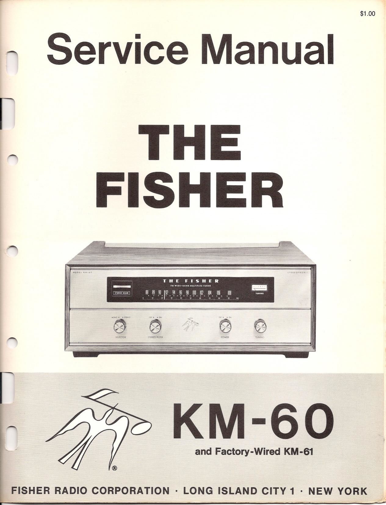
Fisher KM 60 Service Manual
This is the 8 pages manual for Fisher KM 60 Service Manual.
Read or download the pdf for free. If you want to contribute, please upload pdfs to audioservicemanuals.wetransfer.com.
Extracted text from Fisher KM 60 Service Manual (Ocr-read)
Page 1
$1.00
« Service Manual
I. THE
FISHER
IIIE FISHER
and Factory-Wired KM-61
®
FISHER RADIO CORPORATION - LONG ISLAND CITY 1 - NEW YORK
-
Page 2
ALIGNMENT WITHOUT INSTRUMENTS
1. Plug the power cord into a wall outlet and turn the power 8. Turn the meter switch to Position 1. Now carefully adjust
switch ON. While waiting for the tubes to heat up, read the tuning knob to be sure the KM-60 is still tuned to the
through the entire alignment procedures to familiarize station-a slight touch-up may increase the meter reading.
yourself with it. 9 N _ d h | | 3 d IF
. ow It is necessar to re-a 'ust t e imiter coi, r
2- Connect a twin-lead folded dipole antenna to the DIST transformer and 2nd IF transtoIrmer for maximum reading,
(d"l°"') antenna terminals. at the buk 0 the KM-60. using the same procedure as before. Begin first by adjust-
59 "9 meter SWI'CI' '0 P°5'"° 2' ing the limiter coil, then proceed as follows:
3. While watching the meter, tune the FISHER KM-60 from A. Adjust the 3rd IFtransformer from underneath the chassis.
one end of the dial to the other. When it is tuned to a 3- AGli|15tl'=3|'\lHm" the '°P of the "155-
statian, the meter pointer will move upscale (clockwise) (3' MM" 2 'FIW' "dflnw'l "9 "1-
toward "5". Tune in a station that gives 0 reading be- Dr Adjustthe 2nd IF from the top of the chassis.
tween I and 2 on the meter scale. If allstations give meter 10. Next with the tuning knob, tune the KM-éO between
readings greater than 2V m up Pall Of the dipole an- stations in order to pick-u hiss This noise will result in a
tenna or disconnect one of the antenna terminals, while slight meter reading N05, 56' this noise to touch-up"
watching II? meter, to reduce the stgrtal strength. If none the adjustments of the transformers and limiter coil. Adjust
of the stations produce a meter reading greater than I, for maximum meter reading, as follows:
connect the KM-60 to an outdoor rooftop antenna. A Th I w 'I
. e inner col.
4. Use a hex alignment tool to carefully adjust the limiter B. The 3rd IFtransformerfrom underneath the chassis.
coil from the top of the chassis by rotating the tool clock- C- "1! 3'd lFWMlOmererm'he WP 0 "'0 Wm-
wise. If the [ne'er reading decreases (moves toward zero) D. The 2nd IF transformer from underneath the chassis.
rotate the tool counter-clockwise. Continue adjusting until E TI" 2' IF"°"I°""I'°''I" '°F °l 'h' 5,
the meter pointer stops moving upscale (toward 5) and F' Illidrnliffiffillié{Limidfiliflh"w Chmnihmughm
farts 1°.m0Ve 5°ka 4°érjscale- The 50"? OdIUS'me'" is o. The In IF transformer fromtha top at the chassis.
or maximum me er rea mg.
5. N... the or... more...) augment to... and an... 1" Ejjgjfienfi'flofije$333331 2.5333303- 53:553.:
the 3rd IF transformer_for_maximlum meter reading just 05 from underneath the chassis for maximum meter reading.
you d'd the I'm'le' ?'I' FBI adjust the transformer-from Then use the hex tool to adjust the ratio-detector trans-
underneath the chassts. Af'e' reaching a P6,, adIUSl 'I former from the top of the chassis for maximum reading.
from the top of the chassis for a peak reading.
6. Next, adjust the 2nd IF transformer. However, it may not 12' Tum- II'S meter SM: I° P°:"°EMI6-élhls '5 the nolrma:
be possible to peak this transformer properly. When the 'U'9Thl?°5}""°?d°" tune t e d t: a strogg of:
signal becomes strong enough the 3rd and 4th IF - Iim- sthaltlon. 'lss °Uh car'seameterfreha Hay/$600: '
iter stages will begin to limit" so that further increases in T '3 comp etes I e j: tgnment ° .1 e FIS h ,, ow-
signal strength will no longer cause higher meter readings. .2" " rnpy well 8 worth Wh'Ie I° repeat t e mm?
alignment procedure, portlcularly where the tuner will
7. Adjust the 2nd IF transformer from underneath the chassis not be used in a metmpolitan area or if it is desired to
and then adjust it from the top. As before, adjust for a listen to stations more than 20 miles away. Simply leave
peak reading. Should the adjustment not change the the meter in switch position 1 and repeat steps IO, 11
reading, as indicated above, proceed to the next step. and I2.
ALIGNMENT PROCEDURE
Read These Instructions With Extreme Care Before Attempting 2-Turn the Tuning knob maximum counterclockwise. (Dial
Alignment. pointer should line up with calibration mark at the beginning
of the dial. Reset the dial pointer if necessary.)
Test Equipment:
FM Signal Generator, DC VTVM, Oscilloscope. 3~Allow the tuner and test equipment at least 5 minutes
warm-up time. Adjust the line voltage for 117 volts AC 50-60
CI'CSSI cps. Use fully insulated tools: a small screw-driver for trimmer
'l - For the entire alignment procedure, set the Selector Switch capacitors C52, C46, and C36, a K-Tran tool for TI, T2 and
to Mono position, and all level controls to maximum. T3: a hex tool for L1, T5, L6, UT and L12.
STEP DIAL SIGNAL GENERATOR DC VTVM ADJUST INDICATION
GENERAL COUPLING FREQ. MOD.
Set dial Through 220K to n, 72,13 tap and Maximum negative voltage
I Point" 0' 1° unwound I0] MC NM Ten Point 2 bottom and top LI below 5 volts.
(93%er V2 be shield Test Point Maximum negative voltage
2 position l0] MC None 3 T4 top and bottom below to In.
Two 120 ohm carbon 322.5 KC deviation Through 220K to First L12 than
3 MC resistor In series 9° MC at 400 cps. Tut Point3 LII and L6 Adjust for maximum negative
with generator + ' ' voltages and check for
4 m MC Ind, ,0 amen 06 mc _22.5 Kc deviation Through 220K to First c52 than ,in, 40,
"min marked DISY at 400 cps. Test Point 2 C46 and C36