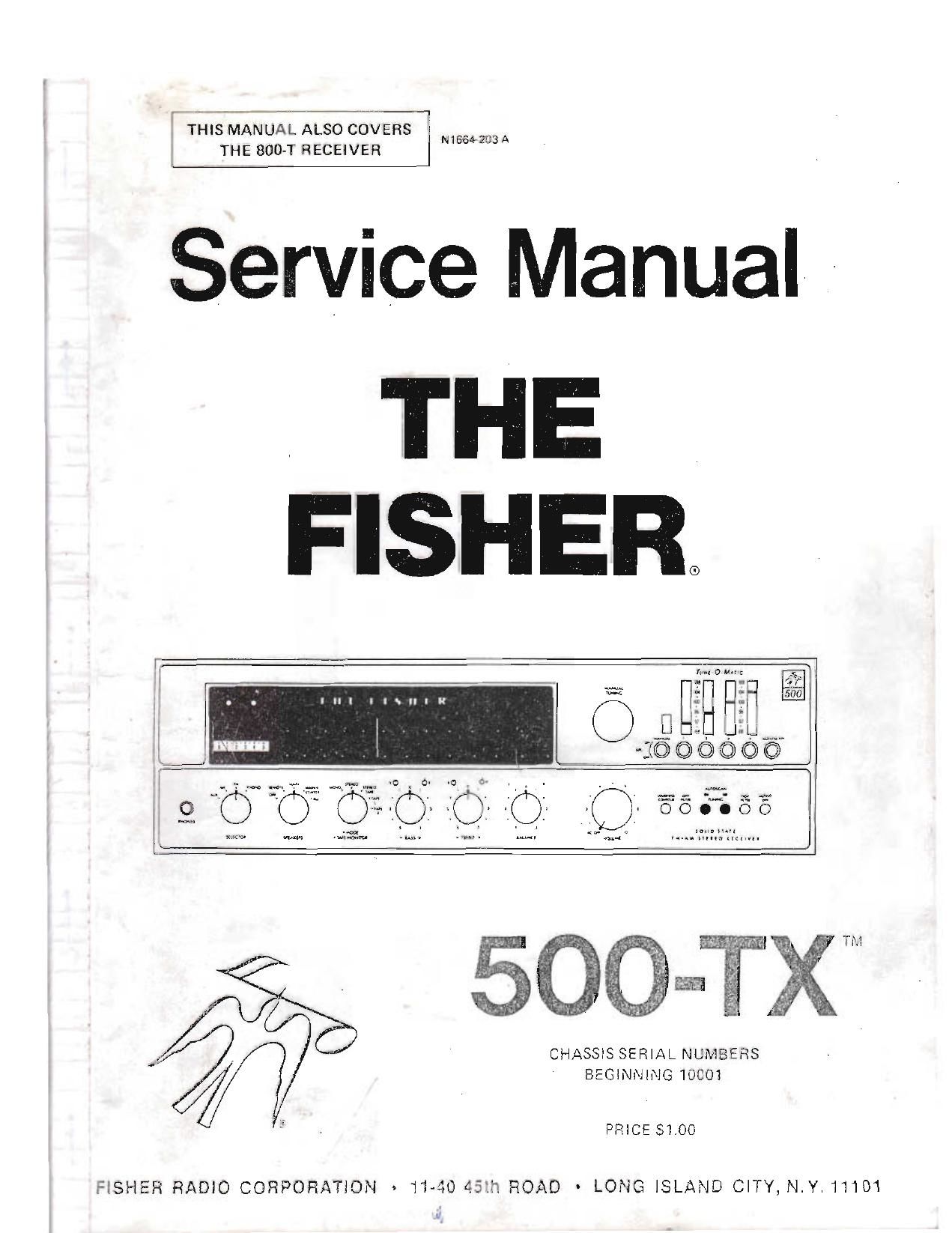
Fisher 500 TX 800 T Service Manual
This is the 38 pages manual for Fisher 500 TX 800 T Service Manual.
Read or download the pdf for free. If you want to contribute, please upload pdfs to audioservicemanuals.wetransfer.com.
Extracted text from Fisher 500 TX 800 T Service Manual (Ocr-read)
Page 1
-I
THIS MANUAL ALSO COVERS .
I N1664 IIJA
THE BOO-T RECEIVER
Service Manual -
THE
FISHER
llhlllu
CHASSIS SERIAL NUMBERS
BEGINNING 10001
PRICE $1.00
FISHER RADIO CORPORATION $ 11-40 4'33. ROAD - LONG ISLAND CITY, N.Y. 11101
Page 2
REQUIRED I
The renew-rig equipment is required [0 completelv tes'. w ~
nu, Vol ut at totransformer or Voltage-t unit or
DC Van, i' iu 'Voltohmmeter
A .vvely C: )r i'ed AC Vacuum Tube Veitmerer
3 Itr It to 100 kHz Minimum)
Oscnioscoi
Low-D tortion Audio (Sine WaveI Generator
~ liLSIaIInn Distortion Analyzer
Harmonic Distortion Analyzer
2 7 Load re5i5t0rs, 8-Ohms,100 Watt IVi'vtiiVi iii iT
AM/FM signal Generator
CAUTION: h s
serviced on / uy
transistor c ",:;
Many of these items are included OI y i i t
are normaI procedures tor expo" . s 2 . .; . .
may be taken, but these olten C '2 55 ' ,,
transistors, circuit components, or pi i
SOLDEFIING: A well-tinned, hot, Clo-i "Iilerr' 1 . i
will make soldering easier, without call , do" - ' i ,
printed circuit board or the CUmpOniliIt' lOI ,
Regular use of a sponge cleaner wll Mai": - t
soldering surface. The heat available at the till 101"
age of the iron) is Important. S( jO-Wa" I i
temperatures of 1,000° F, while a 'irs lNl l '.
solder. Small-diameter tips Should in? used for
connections, pyramid and chisel ms ior 'wu». » . .
Always disconnect the AC power ffWI l' 3m ti'
soldering Turning the power switch r is not s " . '
Power-line leakage paths, through the , 4' g eler ,,_t
iron, may destroy transistors.
PARTS REMOVAL: If a parl is not being returned for lit
warranty factory replacement, it may be cut in half (With
diagonal cutting chars) to make removal easier. Multiple
terminal parts, such as IF transformers, or electrolytic
capacitors, should be removed using special de-soldering (IDS
made especially for this purpose. Removing Solder from
terminals, reduces the possibility of breaking the printed
circuit board when the part is removed.
ACCIDENTAL SHORTS: A clean working area, free of
metal particles, screws, etc., is an important preventive in
avoiding servicing problems, Screws, removed lrom (h:
chassis during sen/rang, should be stored in a box until
needed. While a set is operating, it takes only an instant for a
base-to-CoIIector short to destroy a transistor (and others
direct-coupled to it). In the time it takes for a dropped
machine screw, washer, or screwdriver, to contact a pair of
socket terminals (or terminal and chassis), a transistor can be
ruined.
SOLID-STATE DEVICES: Integrated Circuits Contain the
equivalent of many circuit parts, including transmors, diodes,
resistors, and capacitors. The prelerred troubleshooting pro-
cedure renurres isolating the trouble to one stage using AC
signal tracing methods. Once the Suspected stage is located,
the DC voltages at the Input and output leads are measured to
give an accurate indication of the operating conditions of the
IC. DO NOT use an ohmmeter to check continuity with the
IC mounted on the printed circuit board. Forward Dicslllg the
internal junctions within the IC may burn out the trznsistors.
Do not replace a defective lC Limit 5 external res stors,
capacitors, and transformers are checked rst, to prevent the
replacement IC from failing immediately ring to a defect l"
the connecting components. Solder and unsoldcr eacn IEUXI
separately using a pliers or other heat sink on the lead to
prevent damage Irorn excessive heat. Check that the leads are
BECAUSE ITS PRODUCTS ARE SUBJECT TO CONTINUCLi , I'IU: /EVIENT, FI: l t Il ,' I i
RIGHT TO MODIFY ANY DESIGN OR SPECIFICATION WI I "
EQUIP"
ii n l'rlI'l i - , , 'v i i mini";
:uit
, ade
' , )up
' ' sure
, Jre the
f the
wi"
,i <.
L
the
-t for
: C'H
' " ~ . put
lit ;. l » . .i ")e
, i I . ned
tc )r- - -, . .- - ifiub
out rir 'i, i i . . ii s:zed
.VIE. , ' ' , ,, For
' ' ' ,, mould
wire Iewl'i ,
be used
VOLTAGE MEASUVI.L'.I i , . sured
.\. 'ii -- voimi . - - ', , ' 'i'sured
, l,i ire lilt i . i- ,i n , i i - l :d
Vii :MI'V vti' 5: II." ,, it, , l (ed.
A iu .i V. ,J, ,i ,, . ' i-i ins
., 'i i- ul' ,_F Scllel
ALIGNM:NTPROCEDIIFFi 'i ' I ,iivis'tt
imisn- ,,i I'» - ,
mom virocedr,
JOTICE AND VIITHH ' 't