Fisher 500 T Owners Manual

This is the 23 pages manual for Fisher 500 T Owners Manual.
Read or download the pdf for free. If you want to contribute, please upload pdfs to audioservicemanuals.wetransfer.com.

Page: 1 / 23
Fisher 500 T Owners Manual

Extracted text from Fisher 500 T Owners Manual (Ocr-read)


Page 1

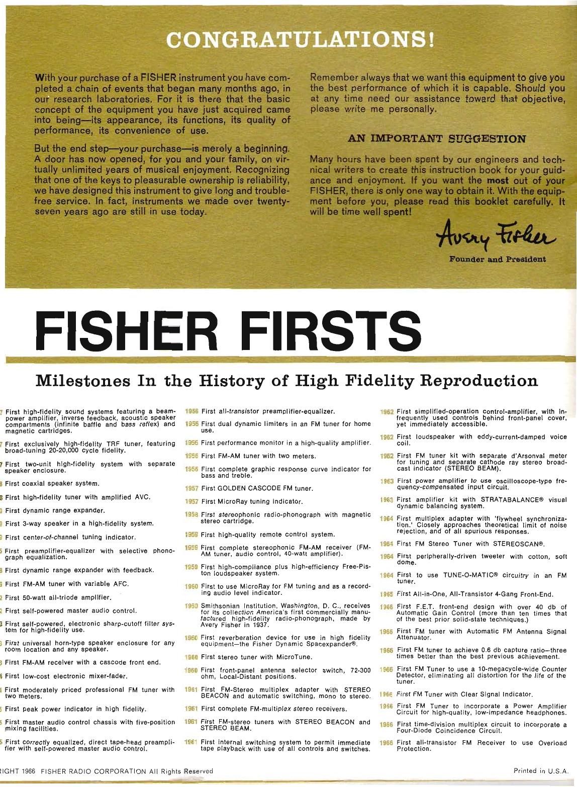
CONGRATULATIONS!

FISHER FIRSTS

Milestones In the History of High Fidelity Reproduction

7 First high-lidelity sound systems lecturing a benm~
power ampliiler. inverse teadback. acoustic speaker
compartments (inlinite baitle and bass rellex) and
magnetic cartridges.

7 First exclusively high»lidelity TRF tuner. ieaturing
broad-tuning zit-20.000 cycle tidellty.

rFirst two-unit high-fidelity system with separate
speaker enclosure.

a First coaxial speaker system.

B First high-IIdBIIIy tuner WItII amplified AVCt
a First dynamic range expander.

9 First 3-way speaker in a high-lidelity system
a First center-oi-channel tuning indicator.

5Flrst preamplifier-equalizer with selective phono-
graph equalization

B First dynamic range expander with ieedback.
a First FM-AM tuner with variable AFC.

2 First 50-watt aII-trlude amplltler.

2 First sell-powered master audio control.

3 First sell-powered, electronic sharp-cutoil tiller sys-
tern tor high-iidellty use.

1 First universal horn-type speaker enclosure tor any
room location and any speaker.

3 First FM-AM receiver with a cascede front end.
t First low-cost electronic mixer-taper.

1 First moderately priced professional FM tuner with
two meters

5 First peak power indicator in high lidelily.

5 First master audio control chassis with live-position
mixing laciiities.

5 First correctly equalized. direct tape-head preampli-
ller with sell-powered master audio control.

1956 First all-transistor preamplifier-equalizer.

i956 First dual dynamic limiters in an FM tuner lor home
use.

1956 First periormshca monitor in a high-quality amplifier.
i955 First FM-AM tuner with two meters.

555 First complete graphic response curve indicator lor
bass and treble.

i95r First GOLDEN CASCODE FM tuner.
i957 First MicroFiay tuning Indicator.

1953 First slereophonlc radio-phonograph with magnetic
stereo cartridge.

i959 First high-quality remote control system.

9 9 First complete stereophonic FM-AM receiver (FM-

AM tuner. audio control. 40-well amplifier).

i255 First high-compliance plus high-eiliciency Free-Pis-
tcn loudspeaker system.

WED First to use MicroRay Ior FM tuning and as a record-
ing audio level indicator.

i950 Smithsonian institution. Washington. D. 0.. receives
lor Its collection America's iirst commercially manu-
lectured high-iidetity radio-phonograph. made by
Avery Fisher in 1937.

i966 First reverberation device ior use in high iideiity
equipment-the Fisher Dynamic Spacexpanaere.

I960 First stereo tuner with Micreruna.

i960 First tront-penel antenna selector switch, 72-300
ohm, Local-Distant positions.

tail First FM-Stereo multiplex adapter with STEREO
BEACON and automatic switching. mono to stereo.

155 First complete FM-multlplex stereo receiverst

I951 First FM-stereo tuners with STEREO BEACON and
STEREO BEAM.

155 First internal switching system to permit immediate
tape playback with use or all controls and switches.

EIGHT1966 FISHER RADIO CORPORATION All Rights Reserved

I862 First simplified-operation control-amplifier. with In-
lrequently used controls behind irent-panel cover.
yet immediately accessible

1962 Firslt loudspeaker with eddy~current-damped voice
OBI t

test First FM tuner klt with separate dArsonvai meter
tor tuning and separate cathode ray stereo bread-
cast indicator (STEREO BEAM).

1963 First power amplifier to use oscilloscope-type tre-
ouency-compensated Input circuit.

196: First amplifier kit with STRATABALANCEO visual
dynamic balancing systam.

196: First multiplex adapter with llywheel synchroniza-
tron. Closely approaches theoretical limit at noise
rejection, and at all spurious responses.

iss-i First FM Stereo Tuner with STEREOSCANE.

IQEJ First peripherally-driven tweeter with cotton. soit
dome.

i964 First to use TUNE-O-MATICVE circuitry in an FM
tuner.

1955 First All-in-One. All-Transistor t-Gang Front-End

I965 First F.E,T. lront-end design with over 40 db at
Automatic Gain Control (more than ten times that
or the best prior solid-state techniques.)

First FM tuner with Automatic FM Antenna Signal
Attenuator.

First FM tuner to achieve are do capture ratio-three
times better than the best previous achievement.

1566 First FM Tuner to use a lO-megacycle»wide Counter
Detector. eliminating all distortion tor the lite OI the
tuner.

ISEE First FM Tuner with Clear Signal Indicator.

lEltiE First FM Tuner to incorporate a Power Amplifier
Circuit tor high-quality. low-impedance headphones.
lass First time-division multiplex circuit to incorporate a
Four~Diode Coincidence Circuit.

1965 First all-transistor
Protection.

FM Receiver to use Overioad

Printed in U.S.A.

Page 2

PRICE $2

OPERATING INSTRUCTIONS
AND WARRANTY

THE FISHER,

5 0 0 -T
; STEREOPHONIC
I FM Receiver

WORLD LEADER IN
STEREOPHONIC HIGH FIDELITY

Page 9

Because the signal is normally stronger near an outside
window, the lead-in of the antenna may be extended with
standard 300-ohm twin-lead" antenna wire so that the
antenna may be placed in the best position. The special
FISHER laboratory dipole antenna, supplied with the
set, will prove to be fully effective except possibly in
weak-signal fringe" areas or where severe reflection
tmulti-path) problems exist,

In strong»signal areas, Where distortion is caused by
signal reflection from other buildings, towers or hills,
it is advisable to use an adjustable, directional indoor
antenna. (Such signal-reflection distortion is termed
multi-path distortion and is similar to the "ghosts" which
sometimes mar television receptiont) Special antennas
are usually available commercially in areas where such
reception problems occur and are of the rabbit-ears"
or telescoping dipole type.

In weak-signal areas, an outdoor antenna is almost a
necessity, especially lor the reception of FM-stereo
broadcasts. Though an omni-directional antenna may
sometimes be satisfactory. directional antenna arrays
are usually advisable In localities where FM broadcast
signals come from several different directions, a re-
motely-controlled antenna rotator is a useful accessory,
If you already have an outdoor VHF television antenna,
it may also be suitable for FM reception. Connect it

temporarily to your receiver-if the results are satisfac-
tory, obtain an antenna coupling transformer so that both
your receiver and the television can be operated from
the same antenna.

When an outdoor FM antenna is used, it is usually con-
nected to the receiver by standard SOD-ohm twin-lead"
antenna wire. Sometimes, if you are located near a busy
highway or in an industrial area, it may be necessary to
use shielded lead-in to prevent disturbing interference
caused by ignition systems or electrical machinery.
Coaxial cable, of 75-ohm impedance, may be used; how-
ever this would necessitate the use ol impedance match-
ing transformers both at the antenna and at the input
to the receiver. Shielded 300-ohm twin-lead antenna wire
is available from major electronic parts dealers and
should be used whenever electrical interference noise
becomes a problem. The two signal conductors are
connected to the NOFIM terminals in the usual manner
and the shield is attached to the hex-head screw nor-
mally used for grounding the record player.

If you are located very close to an FM transmitting sta-
tion, the signal might be so strong that this station could
be received at more spots on the dial than just its as-
signed frequency. In such rare cases, the antenna lead-
in should be connected to the ANT terminals marked
LOC.

SPEAKERS

PLACEMENT

Speaker systems are usually positioned along a wall,
with the provision that no large pieces of furniture block
the sound path between the speakers and the listening
area. Placing the speakers on the floor and in a corner
will emphasize the bass (low frequency) tones.

In a stereo system, the speakers should be placed oppo-
site the listening area. If the listening area is about 10
feet away from the speakers, the stereo-speaker systems
should be at least 5 to 10 feet apart. Increasing the
distance between the speakers will increase the stereo
effect-bringing them closertogetherwill make the stereo
effect less noticeable. Experiment with several speaker
arrangements before making the positions permanent.

Occasionally some furniture arrangements, irregular
room dimensions or echoes from adjacent hallways or
rooms will affect the sound quality, These are individual
problems-there is no cure-aIl-just experiment.

CABLE REQUIREMENTS

For distances of 50 feet or less you may use ordinary
lamp cord or antenna twin lead. Heavier gauge wire
should be used for greater distances to prevent power
losses in the wiring. Do not remove more than a half-
inch of insulation from the ends of the speaker cables.
Any greater length of exposed wire is likely to cause
short circuits at either the speaker terminals on the rear
of the chassis or those on the backs of the speakers
themselves, and may cause a fuse to blow. Twist all ex-
posed strands of wire tightly, so that the ends of the
wire become easy to handle.

To simplify connections (and speaker phasing) use a
cable that will help you to identify the individual wires.
Some types of cable have a ridge, or groove, molded

on one side of the insulation, another type has a colored
thread under the insulation oi one lead.

Do not drive nails through the speaker-cable insulation
if you attach it to the wall, unless the wires are well
separated. Shorts made this way can cause intermittent
or permanent defects-that remain even after the nail
is removed from the point where it went through the
insulation.

PRECAUTIONS

Observe the following general precautions when con-
necting loudspeakers to this receiver; they apply regard-
less of the number of speakers involved:

(1) Make sure that the receiver is turned off and that its
power cord is disconnected from the electrical outlet
before you connect the speakers.

(2) Make sure that your speakers have a rated imped-
ance of not less than 4-ohms. A lower value may cause
severe overload that could eventually blow the SPKR
4A iuse. If this should happen, refer to OUTPUT FUSES
in the MAINTENANCE section of this manual.

(3) To prevent annoying hum and noise, never connect
the COM terminals on the LEFT SPKRS terminal strip
to the COM terminals on the RIGHT SPKRS terminal
strip; also, never connect any at these terminals to
ground or use them as connection points lor the ground
wires oi record players, tape transports, etc. Whether
you use one or more speakers, use a separate wire Irom
each COM terminal to the Com" or and" terminal oi
its corresponding speaker.

(4) Before turning on the receiver, check your connec-
tions both at the speakers and at the receiver. Remove
stray strands of wire shorting one terminal to an adjacent

\l l 1-009 HEIHSH 3H1

Page 18

a; I THE FISHER 500-T

MAINTENANCE

CAUTION: Disconnect the receiver's power cord from
the electrical outlet before performing any of the follow-
ing maintenance or replacement procedures.

CLEANING THE FRONT PANEL

The beautiful gold plating on the control panel borders
will retain its color and brilliance permanently. However,
it is possible that, over a period of time, a film from
atmospheric contamination may dull the surface. Simply
use a soft fresthJaundered cloth dampened with plain
lukewarm water to wipe it clean and the panel will look
new again. Do not use any household cleaning agents or
any cloth that has been used to apply such agents.

CLEANING THE DIAL GLASS

(1) Make certain that the receiver is turned off and that
its power cord is disconnected from the electrical outlet.

(2) Remove all control knobs from the front panel by
grasping each knob in turn and pulling towards you
gently. If you have difficulty in removing the BASS and
TREBLE knobs, try removing the outer section of each
knob first. Do not remove the four rocker switches.

(3) Remove the hex nuts (on the control-shaft bushings)
that hold the front panel to the rest of the receiver
chassis; lift off the panel.

(4) Remove the foam-cushion strips fastened to the re-
taining clips at either end of the dial glass.

(5) Loosen (do not remove) the screws that hold the dial-
glass retaining clips; swing the clips aside and lift off the
dial glass. Because the glass is held from behind by
adhesive rubber strips, it may be necessary to apply a
gentle prying force at the ends.

(6) Remove dust with a dry rag. If you wish to clean
more thoroughly, use a soap-and-water solution only; a
stronger cleaning agent may damage the markings on
the glass.

(7) Replace the dial glass. Make certain to reset it in its
original position by placing it firmly against the lower
left-hand corner of the plastic end frame. Swing the re-
taining clips back into place and tighten the retaining-
clip screws.

(8) Replace the foam-cushion strips, front panel, hex
nuts, and control knobs by reversing the procedures in
steps 2 through 4.

REPLACING DIAL LAMPS

(1) Make certain that the receiver is turned off and that
its power cord is disconnected from the electrical outlet.

(2) Remove all control knobs from the front panel by
grasping each knob in turn and pulling it towards you
gently. If you have difficulty in removing the BASS and
TREBLE knobs, try removing the outer section of each
knob first. Do not remove the four rocker switches.

(3) Remove the hex nuts (on the control-shaft bushings)
that hold the front panel to the rest of the receiver
chassis; lift off the panel.

(4) The dial lamps are spring-clip mounted at either end
of the dial glass. To remove either lamp, gently pull it

out of its clip mount. Replace it with the new dial lamp
(Part Number l50441-1") making certain that the un-
painted side of the lamp faces towards the edge of the
dial glass.

(5) Replace the front panel, hex nuts, and control knobs
by reversing the procedures given in steps 2 and 3.

"NOTE: Replacement lamps may be ordered from your
authorized FISHER dealer or from: Parts Department,
Fisher Radio Corporation, 11-40 45 Road, Long Island
city, New York 11101.

REPLACING THE TUNING-METER LAMP

(1) Make certain that the receiver is turned off and that
its power cord is disconnected from the electrical outlet,

(2) Remove the Phillips»head screws that fasten the top
cover to the receiver chassis; lift off the cover.

(3) The lamp is bracket-mounted directly behind the
tuning meter. Remove the lamp (together with its metal
shade) by pushing it into its socket and turning it counter-
clockwise until it disengages. Keep the shade for use
with the replacement lamp (No. 1847-0F. an extended-
life, frosted version of the standard No. 47 lamp), If your
dealer cannot supply this item you may order it from us
(Fisher Part Number I-50009-B) or you may use a
standard No. 47 lamp instead.

(4) Slide the shade onto the replacement lamp. Line up
the two projecting pins on the lamp with the slots on the
socket; push the lamp into the socket and turn it clock-
wise until it engages, Turn the shade so that the un-
shaded portion of the lamp faces directly towards the
meter.

(5) Replace the top cover and Phillips-head screws.

'NOTE: Replacement lamps may be ordered from: Parts
Department, Fisher Radio Corporation, 11-40 45 Road,
Long Island City, New York 11101.

SERVICING THE STEREO BEACON LAMP

The STEREO BEACON lamp is a long-life device that
should not require replacement in normal use. However,
in the rare event that it should, do not attempt to replace
it yourself; it is not customer serviceable. Consult your
dealer or a qualitied technician for further information
or service.

REPLACING FUSES

CAUTION: Two spare fuses are included in a plastic
bag packed with the receiver. These fuses are not elec-
trically identical; using the wrong fuse in the wrong
receptacle can cause damage to the receiver. Therefore,
please read the following instructions carefully; they
contain detailed information on how to determine the
electrical rating of each fuse and where to use it.

POWER FUSE-The AC power input to the receiver is
fused to protect it against abnormal power-line surges
and other adverse conditions sometimes encountered by
electronic equipment. If the receiver suddenly becomes
completely inoperative (i.e., all dial and indicator lamps
go out and all speakers connected to receiver are silent
at all settings of SELECTOR switch, SPEAKERS switch