Fisher 500 Owners Manual

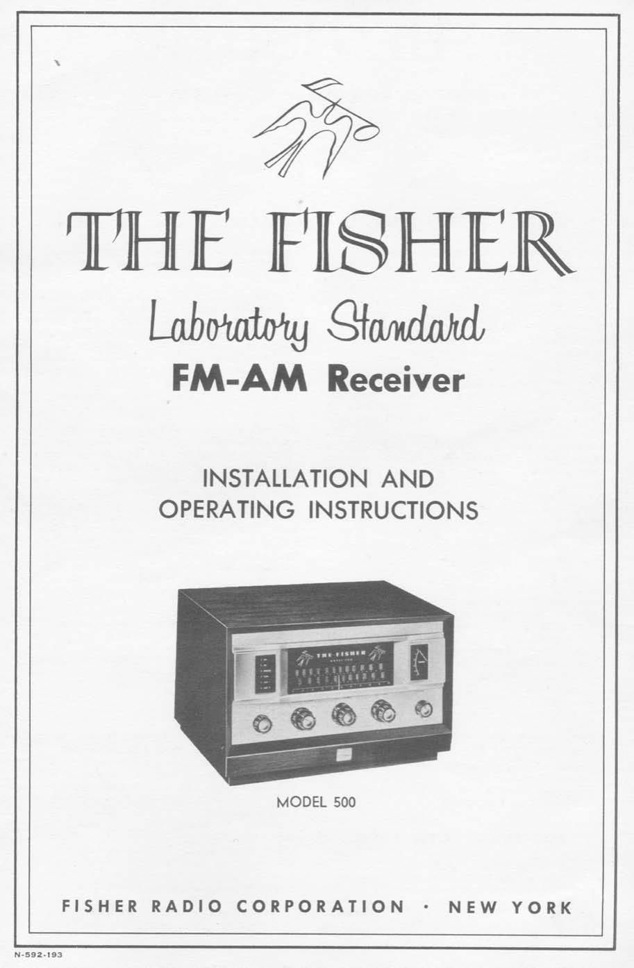
This is the 6 pages manual for Fisher 500 Owners Manual.
Read or download the pdf for free. If you want to contribute, please upload pdfs to audioservicemanuals.wetransfer.com.

Page: 1 / 6
Fisher 500 Owners Manual

Extracted text from Fisher 500 Owners Manual (Ocr-read)


Page 1

rIII-II ~i FISHER
Labmg gm

FM-AM Receiver

INSTALLATION AND
OPERATING INSTRUCTIONS

MODEL 500

FISHER RADIO CORPORATION - NEW YORK

Page 2

THE FISHER

FM-AM RECEIVER ' MODEL 500

GENERAL INFORMATION

THE FISHER FM'AM Receiver, MODEL 500 is
designed to meet the requirements of the most
exacting user, having been planned to profes-
sional standards from the very beginning. With
a full complement of tubes and components for
three complete circuits (FM«AM TUNER, Aumo
Connor. AND SO'WATT Amplifier) the MODEL
500 features an unusually compact chassis of
exceptional design and performance.

The FM section comprises a dual triode, cascode
type, tuned RF stage (for extreme sensitivity and
maximum signal-tonoise ratio) and three [P
stages. These are combined with a full wideband
FM detector for maximum capture ratio. The
AM section employs a tuned RF stage using a
high efficiency FERRITE BAR built'in antenna,
plus provision for an external antenna The diode
detector is of exclusive FISHER design and will
operate with a minimum of distortion under all
conditions. Separate inputs for a standard 300
ohm FM and a conventional AM antenna is prev
vided on the rear skirt of the chassis. A pro'
fessional meter for microaccurate tuning of both
FM and AM, is located on the front panel.

A precision flywheel tuning mechanism with an
anti'backlash feature facilitates smooth and easy
selection of stations. The edge»lighted slide'r'ule
dial has large easy-to-read numerals and a 0 to
100 logging scale for convenient location of the
stations most frequently used. Channel selection
is indicated by a six point light panel located on
the front of the unit. The front panel is of

beautiful, brushed brass, die'cast construction that
will add distinction to any type of installation.

The integrated chassis of the MODEL 5'00 also
includes the audio control, preramplifier and
power amplifier circuits. Audio controls include
a VOLUME CONTROL and a calibrated Loumuass
CONTOUR CONTROL with three separate compenv
sating networks and an off position. The BASS
and TREBLE controls are of the continuously
variable crossvover t pe, concentrically mounted
on a unit assembly or simplified operation.

A complete phonograph and tape preamplifier for
low level magnetic cartridges and direct tape'head
playback is of exclusive FISHER design, comprise
ing a dual triode with feedback for distortion-free
performance. There are four separate and com!
plete equalization settings to compensate for all
of the popular recording characteristics, plus a
correctly equalized setting for NARTB tape play1
back characteristics. Low impedance tape recorder
output permits recording from remote locations
in the home. There are two auxiliary inputs for
connection to the audio section of the MODEL
700 from television, crystal phonograph or the
amplifier output of a complete tape recorder.

The 3vaatt power amplifier uses two type EL37
high fidelity audio output tubes in puslypull
operation for extremely low distortion. All low«
level audio tubes use Dc voltage on the filaments
for maximum signalrto-hum ratio.

INSTALLATION INSTRUCTIONS

THE FISHER MODEL 5'00 includes the following:
i -FM folded dipole indoor antenna
l-AM Ferrite Bar antenna installed in the

chassis
4-Mounting screws and flat washers
2 -- Mounting templates

MECHANICAL INSTALLATION

THE FISHER MODEL 500 is constructed with a
completely selfrcontained front panel, housing the
dial. indicator light and meter assembly. It may
be fitted into custom installations with front
panels up to 5A thick, without the necessity of
extending the control shafts. The 500 may be

installed into THE FISHER Custom Cabinets
for use on a table top or a bookcase shelf. THE
FISHER Custom Cabinets are custom'made in
fine furniture woods and are available in Blonde
(Model TAvSB) and in Mahogany (Model TA«
7M). Installation instructions are supplied with
the cabinets.
To mount the MODEL 500 into a custom instalr
lation or console, the brass front panel assembly
is left intact and the receiver is positioned into
place from the front of the enclosure as follows:
1. Cut a rectangular opening in the front panel
of the enclosure using TEMPLATE No. l.
2. Drill four chassis mounting holes in the shelf
of the enclosure using TEMPLATE No. 2.
Important! Take special note on TEMPLATE