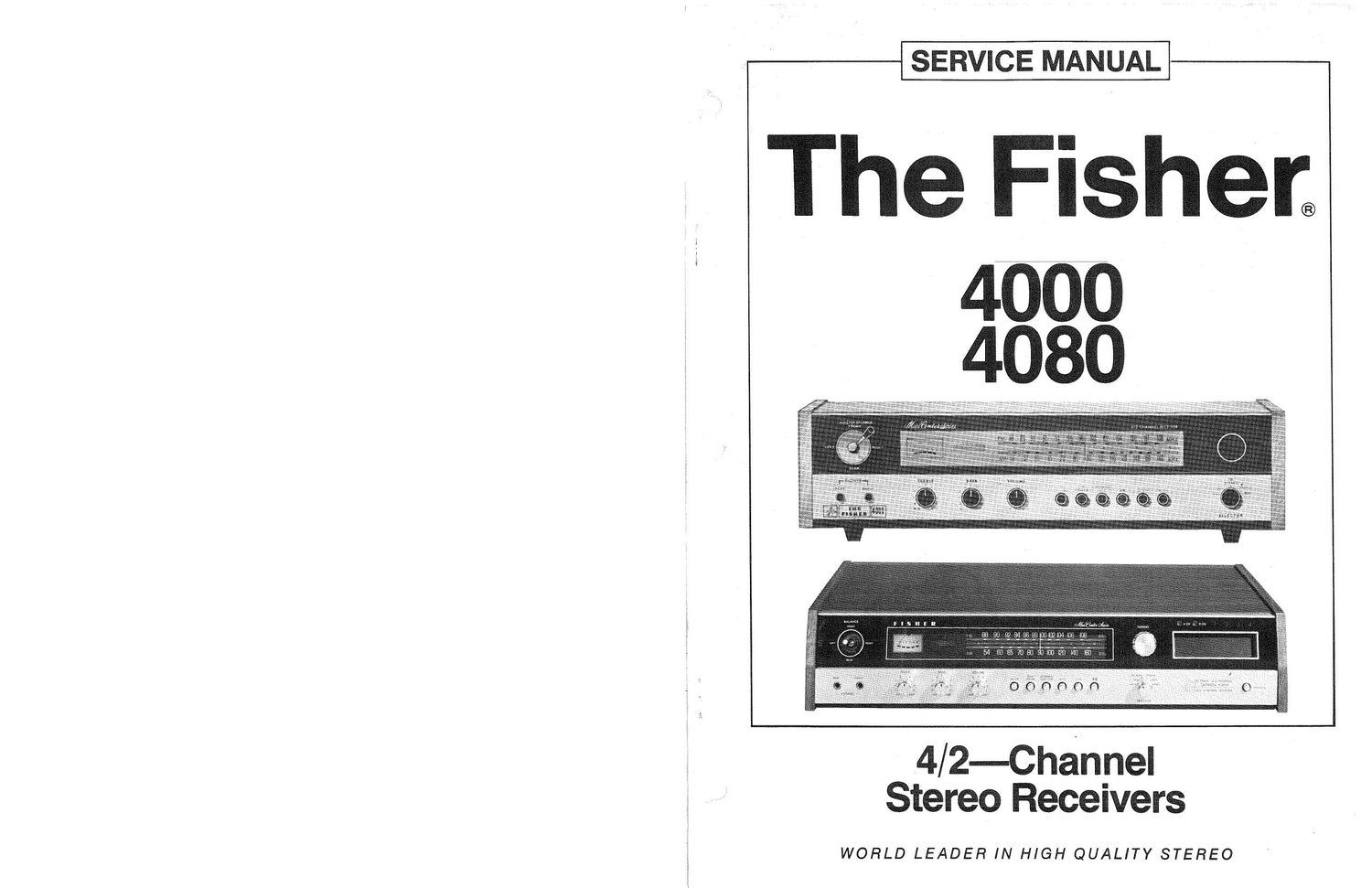
Fisher 4000 4080 Service Manual
This is the 12 pages manual for Fisher 4000 4080 Service Manual.
Read or download the pdf for free. If you want to contribute, please upload pdfs to audioservicemanuals.wetransfer.com.
Extracted text from Fisher 4000 4080 Service Manual (Ocr-read)
Page 1
SERVICE MANUAL
The Fisher;
4/ 2-Channel
Stereo Receivers
WORLD LEADER IN HIGH QUALITY STEREO
Page 2
4000/4080
TABLE OF CONTENTS
Page
Required Test Equipment .......................................... 2
Tape Player exploded View, Parts List and Alignment Procedure .................. 3, 4
AM-FlVl Tuner Alignment Procedure and Layout ........................... 5, 6
Schematic Diagram, AM-FM Tuner, Tape Pre Amplifier, Program Selector and
Power Supply ................................................. 7
Schematic Diagram, Audio Control Amplifier, Switch Board and Control Board ............ 8
Schematic Diagram, Power Amplifier .................................... 9
Schematic Diagram, SO-Decoder and Phone Pre Amplifier ....................... 10
Parts List ........................................... 11, 12, 13, 14
REQUIRED EQUIPMENT
The following test equipment is required to align and to service the Receiver:
0 Line Voltage Autotransformer or Voltage Regulator & Four (4) Load Resistors, B-ohms,
. AC DC Multimeter 50 Watts (Minimum Rating)
i . Accurately Calibrated AC Voltmeter 0 LOWaDlStOltl0ll AM-FlVl Signal Generator
O Oscilloscope (Flat to lOOkHz Minimum) . 10'7 MHZ Sweep-Generator
o Low-Distortion Audio Sine-Wave Generator . Multiplex Generator
0 Harmonic Distortion Analyzer . 455kHZ Sweep Generator
_ This precision high-fidelity instrument should be serviced only by qualified personnel,
CAUTION - trained in the repair of transitorized equipment and printed circuitry.
NOTES
1. The FM IF circuit utilizes a non-tunable ceramic filter which establishes the lF bandpass. To insure symmetrical
tuning and selectivity, the IF must be aligned precisely to the center of the filter bandpass, rather than to 10.7 MHz as in
conventional LC circuits.
; 2. The 120-ohm compostion resistors in series with each lead from the RF generator match the 50 ohm output to the
; 300-ohm input impedance. Generator output voltage is reduced to one~ha|f at antenna terminals. Signal voltages specified
in the FM alignment instructions are generator output levels not antenna voltages.