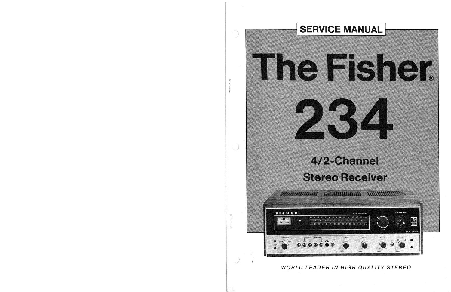
Fisher 234 Service Manual
This is the 10 pages manual for Fisher 234 Service Manual.
Read or download the pdf for free. If you want to contribute, please upload pdfs to audioservicemanuals.wetransfer.com.
Extracted text from Fisher 234 Service Manual (Ocr-read)
Page 1
i
«a
WORLD LEADER IN HIGH QUALITY STEREO
Page 2
TABLE OF CONTENTS
REQUIRED TEST EQUIPMENT ......... 2 PREAMPLIFIER/SO PARTS LIST ......... 7
CHASSIS PARTS LIST ................ 3 PREAMPLIFIER/SO SCHEMATIC ......... 7
HARMONIC DISTORTION TEST ........ 3 AUDIO CONTROL AMPLIFIER PARTS LIST. . 8
TUNER ALIGNMENT PROCEDURES .... 3 AUDIO CONTROL AMPLIFIER SCHEMATIC.. 8
TUNER SCHEMATIC .................. 4 POWER AMPLIFIER PARTS LIST ........... 9
TUNER PARTS LIST .................. 5 POWER AMPLIFIER SCHEMATIC .......... 9
TUNER BOARD LAYOUT ............. 5 POWER SUPPLY/DIAL LAMP SCHEMATIC ... 10
TUNER IC SIGNAL FLOW ............ 6 POWER SUPPLY/DIAL LAMP PARTS LIST t.. IO
TUNER IC DESCRIPTION .............. 6
REQUIRED TEST EQUIPMENT
The following test equipment is required to completely test and align
the 234 Receiver.
0 Line Voltage Autotransformer or Voltage Regulator o Four (4) Load Resistors, 8-ohms, 50 Watts
0 AC DC Multimeter (Minimum Rating)
0 Accurately Calibrated AC Voltmeter o Low-Distortion AM-FM Signal Generator
0 Oscilloscope (Flat to 100 kHz Minimum) 0 10.7 MHz Sweep Generator, Fisher Model 3024
' o Low-Distortion Audio Oscillator or equivalent
o Harmonic Distortion Analyzer 0 455 KHz Sweep Generator, Fisher Model 3025
§ 9 (ID-4 Generator (Fisher 3109 or equivalent) or equivalent
0 Frequency Indicator or Frequency Counter 0 Multiplex Generator, Fisher Model 1536 or equivalent
0 Two (2) RCA Shorting Plugs
CAUT'ON. This precision high-fidelity instrument should be serviced only by qualified personnel,
I trained in the repair of transitorized equipment and printed circuitry.
© COPYFHGHT 1974 FISHER RADIO I All Righls Reserved.
3
I
l
E