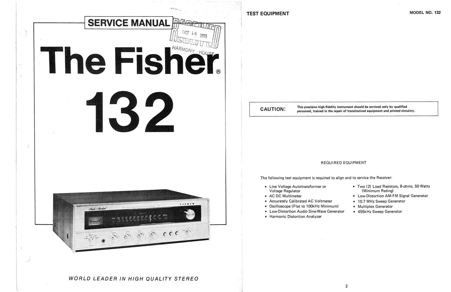
Fisher 132 Service Manual
This is the 8 pages manual for Fisher 132 Service Manual.
Read or download the pdf for free. If you want to contribute, please upload pdfs to audioservicemanuals.wetransfer.com.
Extracted text from Fisher 132 Service Manual (Ocr-read)
Page 1
it
fr
3
3'
1i
my ,
WORLD LEADER IN HIGH QUALITY STEREO
TEST EQUIPMENT
MODEL NO. 132
CAUTION:
This precision high-fidelity instrument should be serviced only by qualified
personnel, trained in the repair of transitorized equipment and printed circuitry.
REQUIRED EQUIPMENT
The following test equipment is required to align and to service the Receiver:
Line Voltage Autotransformer or
Voltage Regulator
AC DC Multimeter
Accurately Calibrated AC Voltmeter
Oscilloscope (Flat to 100kHz Minimum)
Low-Distortion Audio Sine-Wave Generator
Harmonic Distortion Analyzer
0 Two (2) Load Resistors, S-ohms, 50 Watts
(Minimum Rating)
Low-Distortion AM-FM Signal Generator
10.7 MHz Sweep Generator
Multiplex Generator
455kHz Sweep Generator
Page 2
ALIGNMENT
FM-TUNER ALIGNMENT
MODEL NO. 132
SELECTOR to FM, MODE SWITCH to STEREO, VOLUME MINIMUM
Maintain generator output as low as possible for suitable indication.
AM-TUNER ALIGNMENT
SELECTOR to AM, VOLUME MINIMUM.
MODEL NO. 132
Maintain generator output as low as possible for suitable indication.
ITEM
GENERATOR
DIAL SETTING INDICATOR
PROCEDURE
Note: The FM IF circuit utilizes a non-tunable ceramic filter which
tuning and selectivity, the IF must be aligned precisely to the center
conventional LC circuits.
establishes the IF bandpass. To insure symmetrical
of the filter bandpass, rather than to 10.7 MHZ as in
DIAL SETTING
INDICATOR
PROCEDURE
Position of non
interference.
Scope vertical input to
TP4.
See FIGURE 3.
Adjust T101 primary and
secondary for maximum gain.
Repeat above two steps as
required.
See FIGURE 3.
1. IF Connect 10.7 MHZ sweep Position of non» Scope vertical input Adjust first T201, then T200
ALIGNMENT generator in series with a interference. TPZ through DIODE for maximum gain and
; 33K ohm resistor to TP1. IN 4148, 100K resistor symmetry.
i Connect ground lead to and 100pF capacitor as See FIGURE 1.
TP7. Markers are not shown. Connect ground
; required. lead to chassis.
2. PRELIMINARY As above. As above. Scope vertical input to Adjust T202 top and Bottom
g DETECTOR TP3 through a 100K for maximum gain and
ALIGNMENT resistor and IOOpF symmetry.
capacitor as shown. See FIGURE 2.
Center of GOOkHz
calibration mark
on dial.
Scope and VTVIVI to
RCDR OUT jack.
Adjust L101 (OSC) and
L102 (Loop ANT) for
maximum.
Note: 120-ohm composition resistors in series
with each lead from the RF generator match the 50~ohm output to the
BOO-ohm input impedance. Generator output voltage is reduced to one-half at antenna termin
aIs. Signal voltages
specified in this table are generator output levels, not antenna voltages.
ALIGNMENT
ITEM GENERATOR
1. AM IF Connect 455kHz sweep
generator to AM-EXT-
ANT. and GND. terminals.
Note: After each adjust-
ment reduce generator
output as required.
2. AM AM generator to AM-
FRONT END EXT-ANT and GND
ALIGNMENT terminals. Set to 600kHz.
Modulate with 30%, lkHz.
3. AM Change frequency to
FRONT END 1400 kHz.
ALIGNMENT
Center of 1400kHz
calibration mark on
dial.
As above.
Adjust TC102 (OSC) and
TC101 (ANT.) for maximum.
Repeat steps 2 and 3 until
optimum alignment is
reached.
3. FRONT END Tuning knob Center dial pointer on D
ALIGNMENT fully CCW. and cement it in place.
4. Connect FM RF genera- Center of 90 MHz Scope vertical input Adjust L213 then L212
tor through two 120-ohm calibration mark and AC-VTVM to for maximum gain.
resistors to FM ANT screw on dial. Recorder Output. Repeat above step as
terminals. Set generator to required.
~ 90 MHZ, modulate with
j 400 Hz to provide 1:75
5 deviation. Set generator
output attenuator as
low as possible.
5. Change generator setting Center of 106 MHZ As above. Adjust TC213 for maximum.
to 106 MHz. calibration mark on Adjust TC212 then TC211
dial. for maximum gain.
Repeat the two steps above
as required.
, 6. FINAL As above, except set to Position of none Scope vertical input, Adjust T202 bottom slug
DETECTOR position of non-interfer- interference near distortion meter and for minimum distortion,
ALIGNMENT ence near 100 MHZ. Set 100 MHZ. ACAVTVM to Record- and then set VR 201 for
. generator output attenUv Output. 1.1V on AC-VTVM.
: ator to 2mV.
3 7. STEREO As above, (Step 6) except As above Step 6. Scope and AC'VTVM Adjust first VR-302 and
2 SEPARATION modulation.
Modulate LEFT Channel
i67.5l
pilot carrier.
to Right Recorder
output. Observe
STEREO-BEACON
LIGHT.
then VR-301 for minimum
output. Repeat the 2 steps
as required.
LIUI
awesc
AM-FM TUNER LAYOUT
AM-KF FM-IF
rcaé an rcziz rcloz FM-OSC no: 2m
\ FM.AM-IF
FM-RF FM-osc \ "52
LEI! Lzls
FIIHF
r200
H H H lsI H H H H H
STEREO ssmnou
musr
VR3OI
vasoa
rM-Rmo
DETECTOR
r 202
milk
J VR ZOI
©
l
l
I!
19km ADJUST I
/
I
/ m- MPX ism:
l
l
I
E
«I
LEVEL ADJUST
I-E IOODF
FIGURE I
FM- IF
FIGURE 2
FM-RAIIO
DETECTOR
100K