Ferrograph Y 722 Service Manual

This is the 74 pages manual for Ferrograph Y 722 Service Manual.
Read or download the pdf for free. If you want to contribute, please upload pdfs to audioservicemanuals.wetransfer.com.

Page: 1 / 74
Ferrograph Y 722 Service Manual

Extracted text from Ferrograph Y 722 Service Manual (Ocr-read)


Page 1

Y722
Y722"
Y722L
TIZ
Y72lL

FERROGRAPH

SERIES SEVEN SECTION1

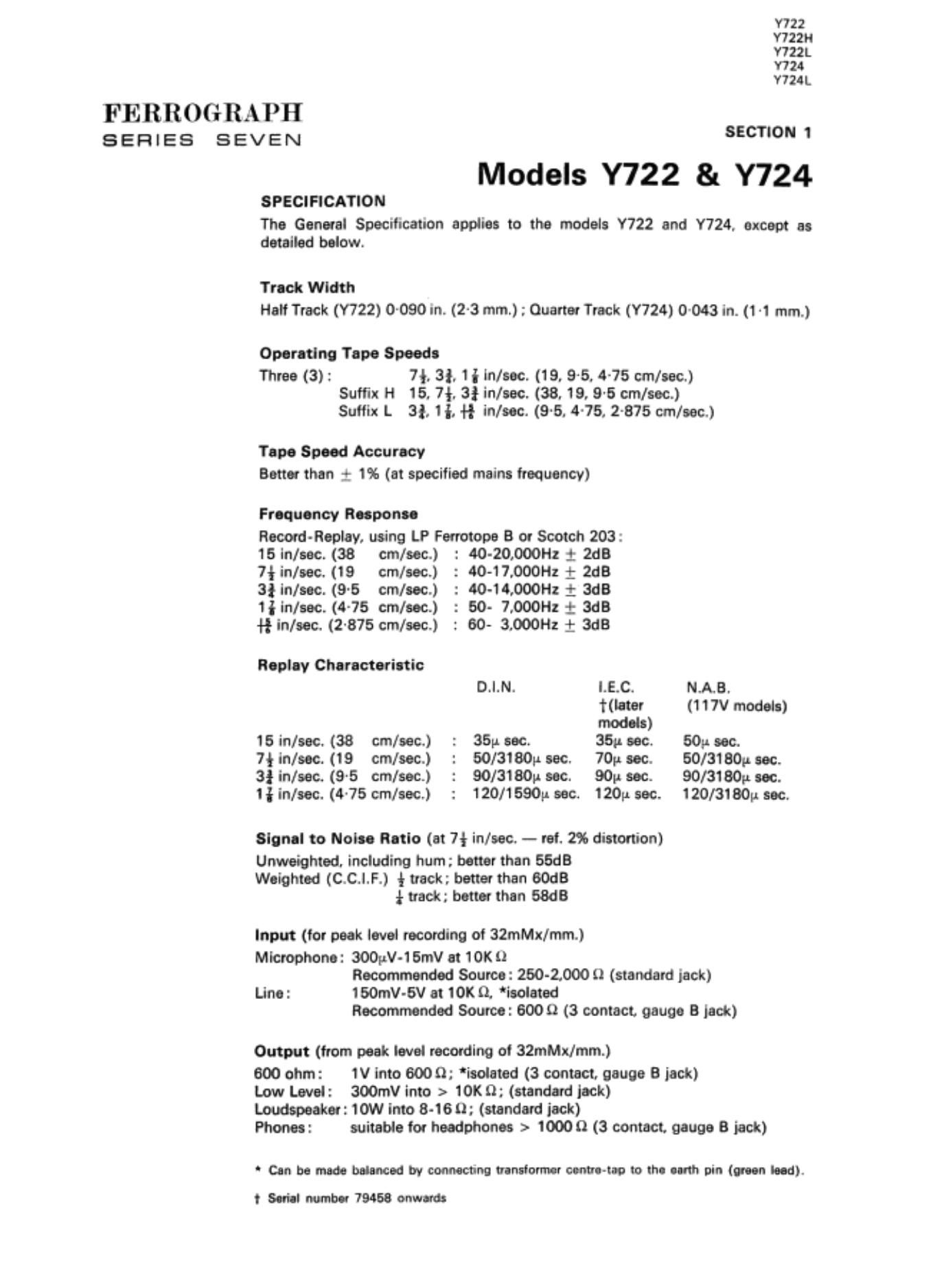
Models Y722 & Y724
SPECIFICATION

The General Specification applies to the models Y722 and Y724, except as
detailed below.

Track Width
Hail Track (Y722) 0090 in. (2-3 mm.) ; Quarter Truck (Y724) 0-043 in. (1 1 mm.)

Operating Tape Speede

Three (3): 7*. 3i, 1iln/sec. (19, 95. 4-75 cm/sac.)
Suffix H 15. 7f. 3} in/eec. (38. 19, 9-5 cm/sec.)
Suiiix L 3!, ii. {if ln/eec. (9'5. 475, 2-875 cm/aeo)

Tape Speed Accuracy
Better than 1 1% (at specified mains frequency)

Frequency Reeponee

Reoord- Replay. using LP Forrotope B or Scotch 203:

15 in/sec. (38 cm/eec.) : 40- 20000Hz + 2113
7iin/eec. (19 cm/eec.) : 40-17000Hz 1- 2d8

3! in/aec. (9'5 cm/aec.) : 40-14,000Hz 1 ads

1} in/eec. (4.75 cm/eec.) : 60- 7.00011: t 3d8

H in/eec. (2.875 cm/sec.) : 60- 3.000112 1: 3dB

Replay Characteristic

D.|.N. LEC. N.A.B.
later (117V models)
models)
15 in/sac. (38 cm/eeo) : 35;: sec. 35.- eec. 50;: sec.

7} him. (19 cm/eec.) : 50/3pr sac. 70p. aec. 50/3180p aec.
3} in/sec. (9~5 cm/sec.) : 90/3180» sec. 90p sec. 90/3180p sec.
1 in/oec. (4-75 cmleec.) : 120/1590p sec. 120p. sec. 120/3180 sec.

Signal to Nolae Ratio (at 7* in/aao - ref. 2% distortion)

Unweiphted. including hum; better than 55dB
Weighted (C.C.I.F.) (track; betterthan 60dB
* track; better than 6MB

Input (for peak level recording of 32me/mm.)
Microphone: 300pV-15mv at 10K i)

Recommended Source: 260-1000 11 (standard jack)
Line: 150mV-6V at 10K 0. isolated

Recommended Source: 6000 (3 contact. gauge B lack)

Output (from peak level recording oi 32me/mm.)

600 ohm: 1V into 6009; 'iaoieted (3 contact. gauge B jack)

Low Level: 300mV into > 101}; (standard jock)

Loudspeaker: 10W into 8-160: (standard jock)

Phones: suitable for headphones > 1000 Q (3 contact. gauge 8 jack)

Can be made nuanced Irv connecting tranalormer oermatep to the eerth pin (ween teed).
t Seriel number 19458 onwards

Page 2

FIG. 1. EXPLODED VIEW OF TAPE-DECK (PARTS LIST IDENTIFICATION)

Page 3

FIG. 2. AMPLIFIER-STEREO. FIGHT VIEW

FIG. 3. AM'Uflll-STEIEO. REAR VIEW

(er - ()pr

Page 28

FER]

BEFHl

. . . and if the earthed tension arm toucha the insulated pillar, it triggers the delay
circuit (R111. R112. C106). if the pillar is earthed for more than 1 l secs. approx..
transistors VT100 8 W1 01 conduct and operate RL100. If the pillar is discon-
nected from earth before VTlOO conducts. the delay circuit resets and the fault
relay is not energised.

With the Record button operated and locked in the Record position. a right-
angled arm on the record lever operates two micro-switches SW10? and SW108.
Contacts of SWIOB. which normally short circuit the outptrt of the record ampli-
fiers to earth vie P100/SK100 pins 1 and 9 (pin 9 only on mono models), are
opened. Miaoawitch SW107 contacts route the 50 volt d.c. supply, via P100/
SKlOO pins 7 and a. to the amplifier where it performs the following functions:

(i) Provides a positive 50 volts d.c. for the 100 ltliz oscillator.

(ii) On models prior to Serial No. 76,000. energisee relay flL700, whose
contact RL7OOB switches the record signal. via Output switch SW02. to
the W meter (also RLIOOA on stereo models).

Tape Tension (Fig. 3)

127 Tape snatch on stopping and starting is eliminated by two differentiallwdampad
tape tensioning arms. The left-hand arm assembly is mounted on the underside
of the deck control panel, and the right-hand am. is mounted on the raised platform
to the right of the pinch roller. Both arms are fitted with a differential brake.
employing a nylon tape tonsioned by a spring. On later models the right-hand arm
tension is adjustable for vertical or horisontal operation of the deck by turning
the slot to 'V or 'H' respectively.

Auto-atop and Foil Stop (Figs. 8, 27 and 28)

128 The auto-stop and foil stop are two oi the three safety devices which automatically
inhibit the tape deck chive when they are operated. In each case. relay RUOO
is energised by completing the earth return cicuit of its operating coll. Relay
contact RU 003 open-circuits the 24 volt d.c. supply to start solenoid L100,
at the same time completing the 24 volt d.c. supply circuit to the red Reset lamp.
which lights. One safety device. the setting oi the Speed Conan! and Equalisatlon
switches. has been explained in paragraph 110 and the othertwo are asfollows:

(i) The right-hand damping arm (paragraph 127) is normally held in its
operating position by the tape, but should the tape run out or be incorrectly
loaded (i.e. not on the arm), then the arm is pulled into contact with an
insulated pillar by a spring. The insulated pillar is connected to the
negative side of the relay RU 00. and if the eerthed tension arm touches
the insulated pillar the circuit of HUD!) is completed and the relay operates.

(ii) The tape guide. between the left-hand tension am and the supply reel:
is an insulated pillar mounted on the deck cover plate. This pillar is con-
nected to the negative side oi relay RL100, and if the metallic fol on the
end of the tape makes contact with the insulated pillar and the tensioning
arm. then the circuit of RL100 is completed and the relay operates.

Note: Contact BMW is a hold-on contact, and when operated completes the
negative circuit of the replay even it the fault condition is removed. To
de-energise the euto~etop relay, the fault must be cleared and the
function control SW100 switched to Stop.

Turns Counter and Lamps (Figs. 8. 27 and 23)

129 A turns counter mechanism and two lampholders are fixed to a panel which is
mounted above the idler wheel assembly. The panel is fixed to the main assembly
by two lugs at the front, which fit into slots at the rear of the raised platform, and a
screw at the rear of the panel which clamps it to a stand-off pillar. Attached to the
left-hand side of the panel is an arm which stops the idler wheel arms from moving
out of their retaining slots.

1 7
Para. 128 Serial No. 78.800/2 onwards

The action of the Auto Stop now has a built~in delay of approx. 1 l seconds. but
also operates if there is a loss of tape tension. Para. 128 (i) should now read :-

Page 36

FE RROGRAPH

SERIES SEVEN

168

167

188

169

E - General Overhaul

Before proceeding with the general overhaul strip the recorder as follows:
(i) Remove the recorder from its case as detailed in Section 3.

(ii) Remove the deck cover plate as detailed in Section 3.

(iii) Remove the deck control panel as detailed in Section 3.

(iv) Replace the Speed. Fastwind end function control knobs, and the auto-
etop arm guide.

Thoroughly clean, with the brush provided, any dirt. dust or tape oxide from the
tape transport system. paying particula attention to the following:

(i) Heed assembly (record and replay heed faces should have a polished
finish).

(ii) Tape guides.

(iii) Capstan spindle. r _

(M Pinch Roller. JR use slightiy damped. fluff-free cloth.

(v) Guides on tape tansioning arms (one mounted on deck control panel).

(Vi) Preserve pads (replace if hard or damaged).

Warning: Do not use abrasives. If accumulation of tape oxide is excessive.

use methylated spirits.

Clear any dirt. dust. tape oxide or solidified greae from the tape deck chassis and
mechanism. paying panicqu attention to the following:

(i) Cepsten motor pulley.

(ii) Idler wheels.

(iii) Flywheel.

(iv) Self-wrapping brakes.

(v) Constant friction brake pad (replace if hard or damaged).

(vi) Cam mechanism of the function control.

(vii) Lock Release assembly.

(viii) Loading arm leaf spring.

(ix) Record micro-switch assembly (SW107 and SW108).

(x) Solenoid pole pieces: theee should be free from obstruction.

(xi) Foam pads; these should be firmly attached to the solenoid armawres to
minimise mechanical noise.

(xii) Spool height adjuster assembly.

(xiii) Start lever pivot.

(xiv) Run lever pivot.

(xv) Record lever pivot.

(xvi) Record release arm.

(xvii) Tums counter and flexible drive.

Uphtly oil the following points. using a highfy refined straight mineral oil such
as Shell Tellus 27, Aaroshell No. 3. etc:

(i) Idler wheel bushes (see Section 3 for access to bushes).

26

Page 50

FERROGRAPH
SERIES SEVEN

331

333

334

335

Before replacing the capstan motor ensure that the anti-vibration mountinge are
in good condition. To replace the capstan motor aseenbly reverse the removal
procedure. While doing so. ensure that the motor pulley is centrally situated
through the hole in the deck plate. or the idler wheels may not engage properly.

Removal/replacement of pinch roller arm (Fig. 8)

To remove the pinch roller arm proceed as follows:

(i) Remove the recorder from case as detailed in paragraph 301.

(ii) Remove the deck cover plate as detailed in paregaph 303.

(iii) Remove the deck control panel as detailed in paragraph 305.

(iv) Remove amplifier assembly as detailed in paragraph 307.

(v) Remove the two screws and locking plate (no plate on earlier models)
securing the pinch roller bracket to the pinch roller arm and remove the
pinch roller and bracket.

(vi) Remove the pinch roller arm return spring from the tag on the pinch roller
arm.

(vii) Remove the micro-switch SW106 actuating arm.

(viii) Remove the two counter-balance weights by unscrewing the weights and
spindles froth the pinch roller arm (no weight: fitted on modified arm of
later models).

(ix) Remove the screw (fromthebottom) and '6' clip (from the top) ofthepivot
spindle and withdraw pivot spindle from the bottom of the tape deck
chaeeia.

()0 Ease the pinch roller arm clear of the assembly from the front.

ToreplacethepinchmllerarmreversedierunovalprocedueAfteruwphch
roller arm has been replaced, the gap between armature and the pinch roller
arm must be set correctly as detailed in Section 4A paragraph 406.

Removal/replacement of spindle end/or flywheel (Figs. 8 and 10)

To remove the spindle and/or flywheel proceed as follows:

(i) Remove the pinch roller arm as detailed in paragraph 332.

(ii) Remove the screw from the lower and of the flywheel spindle (Fig. 10).

(iii) Slacken the pinch clamp which is located just above the ate-face of the
flywheel.

(iv) Withdraw the capstan spindle upwards.

(v) Lift the flywheel clear of the lower flywheel bearing and remove from the
recorder.

Before replacing the flywheel ensure that the spring is fbmly fitted to the top
and grease the spring and lower flywheel bearing using a high viscosity grease.
On later models the spring has been replaced by a fixed pin in the flywheel. To
replace the flywheel reverse the removal procedure, fitting the spindle so that
the lower end is almost flush with the bottom bearing plate but slightly rapeseed
into the bearing.

Note: After replacing the flywheel. check the adiustment of the gimbal bearing

and flywheel as detailed in Section 4A.

Removal/replacement of head assembly (Figs. 3. 5 and 9)

To remove the head aseel'hbly proceed as follows:

(i) Remove the recorder from case as detailed in paragraph 301.
(ii) Remove the deck control panel as detailed in paregeph 306.

45

Page 52

FERROGRAPH

SERIES SEVEN

339

(v) Unooldor tho Ioodo to tho hood pino. noting to which pin tho braid lo
ooldorod (normally tho loft-hood pin viewed from flout tooo) and on
ouroo modolo which lood is outdorod to tho routwo pino (Uppor Track).

(vi) Remove the tow ocrowt which futon tho hoods to the mounting ploto.
On the Record and Reploy hoodo take care not to Iooo tho opting under tho
oodzot-hoodod ocrow at the front left of each head.

To roploco o hood. mono tho romovol pmooduro, mooring that tho springs oro
toflttod to tho Rooord ond Roploy hoods. Nut o Record or Roploy hood hoo boon
roplocod (or rofltud) and tho hood block romountod. it must ho ro-ollgnod
corroctly. Tho oockot-hoodod olioning wow (Fig. 9) should bo oot on tho: tho
hood con oppouo vonlcot. thou tho hoight ohockod oo in Fig. 12. Tho hood holght
io odiumd by inooning or "moving thin ohimsof B.P. (or non-moonotic motoriol)
botwoon tho hood and it: mounting ploto, and rotightoning tho fixing oaowo.
Aotholuodfooorrunotromoinvonicotohimoodoquol hoightnmboinoonod
from ond root. Tho w azimuth olignmont should then ho oot oocuroton oo In
porogroph 420 or 426.

47

Page 58

FERROGRAPH

SERIES SEVEN

(iv) On the playback heed pressure pad ensure that the Mu-Metal Wing is
lockedintheconectpoaitionsuchthatthepadismaklngpropercontect
with the head face, and the wing is not fouling the tape.

Cut-Out Switches and Damping Arms
408 To check the operation of the cut-out switches and damping arms proceed as
follows:

(i) Replace the deck control panel as detailed in Section 3 paragraph 306.

(ii) Load the recorder with 8 in. reels and ensure that almost all the tape is
on the take-up real, as this is the most critical condition.

(iii) Switch On recorder and observe the operation of the tape transport in
all positions of the function control. Chock that the spring ol the right-hand
tape tension/auto-stop arm is not so strong that the arm traps the tape
continuously against the insulated auto-atop pillar. However, it is normal
forittotrapthetapoon stating to run,whilethetalte-upreel is picking up
speed.

(iv) Switch the function control to Pause and unloop tape from right-hand
guide. Enmro that when left free the arm touches the "live' euto- op
pillar, lighting the Rose! lamp and switching off the motors. c 4;. I; (13;:

(v) Replace mpe and chock that Reset lamp is still lit and that the function
control has to be switched to Stop before lamp is extinguished.

(vi) Ensure that when the left-hand guide and the tape damping errn are bridged
by tho metal foil on the tape. the auto-stop relay is tripped and the Reset
lamp llghts.

tape Transport
409 Tocheckdteconectoperetionofthetepetranaportsyatam proceed aelollows:

(i) Load a tape on the recorder and switch On. Turn the function control to
Run and observe the tape running. There m be no "Marco of tape
buckling due to guides being incorrectly set.

(ii) Check the setting of the spool height adjusters and see that the tape does
not scrape on the spool rim At the lowest setting of the spool height
adjusters the edges ot the tape must not scrape on the plastic supports of
the cover box.

(iii) Check ease oi tape loading.

Capetan and Ftywheol
410 To check the correct operation of the capstan and flywheel proceed as follows:
(i) Grasp the flywheel and the capstan spindle (Fig. 8) - there should be
slight end play and a very small rotary movement bemoan the two
components.

(ii) The freedom of the gimbal bearing can be observed on a W. a F. meter
as in paragraph 415 by gently pressing either side of the gimbal, when
a change in the tape speed should be observed. There should be a com-
plete rotum to normal on releasing the pressure on the bearing.

(iii) Set the recorder to Run at 7* in/sec (19 cm/sec), then return to Stop.
Check that the flywheel runs for anoreximetely 45 seconds after switch oft.

Friction Brake
411 To check the correct operation of the friction brake proceed as follows:
(i) Check that the lever is free moving.

64

Page 73

Y722
YTZZH
V7221.
W24
W24 L

FERROGRAPH
SERIES SEVEN

Models Y722 & Y724
GENERAL DETAILS

The Models Y722 Er Y724 are basically very similar to the Models 722 a 724
respectively. and the some servicing details apply.f The Line inputs and 600 ohm
outptns are fitted with isolating transformers and 3 contact. gauge B lack sockets.
making them suitable for connection to 6000 lines.

Phones Output

The Phone: output. on the side of the cabinet. gives an output suitable lor stereo
headphones with an impedance at 10000 or greater and wired to a standard
stereo phones jack (3 contact. gauge A). Mono headphones wired to a standard
jack (2 contact. gauge A) can also be plugged in, when the Upper Track signal
will be heard. The signal levels are adjusted by the respective Output controls.

Speaker Switch

The Speaker switch. also on the side of the cabinet. can be used to switch of! the
internal loudspeakers it not required. usually when the Output controls are used to
adjust the signal leveis at the Phones output.

SERVICING

The servicing procedure for the Models Y722 e Y724 is the same as described
for the Moods 722 e 724 respectively.t

I 17)

Ur; I/s "W
F unoruouts
.. :Lr-J 3|
Jinn
rem
u l u
_ eras sun
can 0/! urea rem
anus not are:

Y722 O V714
cm Rd, Part No. CW Rel. Perl No.
R733 Resistor 10K 0 {W 20% 626-00-10K .IK700 Jack Sochst. 2 WW 692.011
R734 Resistor 10K (I fill 20% 025-00-10K JK701 Jack Socket. 2 way 692-0
R736 minor 30 0 w 10% 5-07-31 JK70¢ Jack Socket. 3 way - gauge 3 092-015
R738 Resistor 330 a W l0! 026-177-330 JK705 Jack Socket. 3 way - W I! 692-015
R737 fleaiator 39 n 10% WMIound BPIZSOOIR JK708 Jack Socket. 3 way - gauge 0 692-016
ens Rainer 39 D 10% W.Wound SPIN/R JK709 Jack Socket. 3 way - gauge B 692-015

JK710 Jack Socket~ 3 way - gauge A 692-010
W705 Speaker Switch m-oos P704 Plug. 4 way 577-

P705 Plug, 0 way 577-009

3004 Social. 4 way 652-010
TR70I Translorrner MC/Tl 702M 8K705 Socket. 4 way 692-01 0
TR702 Tremtorrner MC/Tl 702M
111703 Trimming MCI 297A LS700 Loudludl (30 D) 700v
I704 Transformer MC/297A L570! Loudspeaker (30 0) 700-000

1 Later models (Serial No, 78450 onwards) are equalised to the LEG. characteristic.