Ferrograph 713 Service Manual

This is the 40 pages manual for Ferrograph 713 Service Manual.
Read or download the pdf for free. If you want to contribute, please upload pdfs to audioservicemanuals.wetransfer.com.

Page: 1 / 40
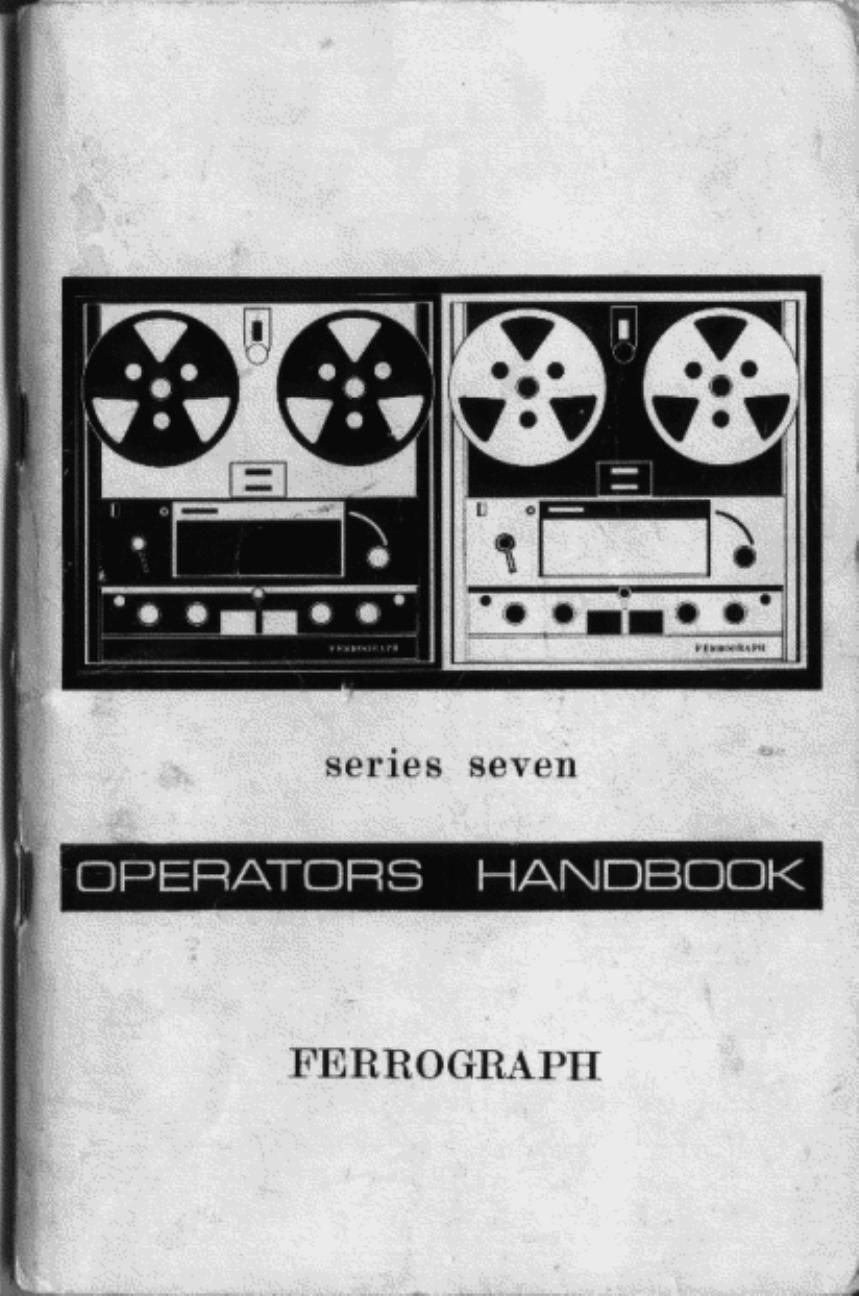
Ferrograph 713 Service Manual

Extracted text from Ferrograph 713 Service Manual (Ocr-read)


Page 1

series seven

L OPERATORS HANDBOOK

FEHROGRAPH

Page 2

MID-ODD. ISSUE 4

OPERATOR'S HANDBOOK

Farragmph

SERIES SEVEN. MK 2

SEFIIAL NUMBER 78.800/2 ONWAHDB

THE FERROGRAPH COMPANY LID.
IONDON AND SOUTH SHIELDS

Page 20

The maximum volume (With the variable resistance at maximum) is
still governed by the Output control on the recorder. but adjusting the
remote control wrll vary the stgnal from this down to zero.

Sign-l Opuutlon

The Auxiliary Socket on the rear panel IS arranged to accept a Signal
operated Swrtching Unit. This unit is designed to drive the tape only
when a signal is present for recording and to switch 0" the tape drive
when the signal ceases. To allow tor short gaps in the Signal 9.9. pauses
in speech. the Swrlching Unit has a burlt-in delay at 5-25 secs. before
swrtching 0", Thus by omitting the long silent periods when no signal
occurs. messages. etc. spread over a long time can be recorded onto
a srngle tape.

After plugging the Swrtching Unit into the Auxrlrary Socket. the
recorder should be set In the "Pause" position With the "Record" button
pressed and the record gain controls adjusted to ore-deterrnined
settings. The appropriate Output Switch must be m to "Source".

SPECIAL APPLICATIONS

Echo Efloct

Due to the phv5ical spacrng of the record and replay heads there is a
linite delay between the record and replay Signals which corresponds
to the time taken for the tape to travel between the two heads. At

§ in/sec. this is approximately .5 sec (a, sec. at 15 in/sec.. 5 sec. at
3} in/sec . 3 sec. at I; in/sec.). Thus part of the replay Signal fed back
into the record amplifier Will give the effect of an echo whose magnitude
wrll depend upon the amount ol Signal led back.

The Meter swrtch should be set to "Source" and the Output switch
to "Tape". A lead should then be connected between the 600 ohm
output and the Line input (Line gain control at zero). The signal to be
recorded should be led into the Microohone input. and its gain control
advanced to a suitable record level. On turning to Run and pressing
the Record button. the echo can be added to the recrxd signal by
gradually turning up the Line gain control Care should be taken not
to set lhe echo too high as this may cause it to build up, leading to
instability.

When applying echo to a storeophonic recording. each channel
should be connected as described above. taking care to adlust the
controls to give aporoxrmatelv the same amount 01 echo to each channel,
unless an unbalance is intentionally required.

36

let

FOG. 13. HEAD BLOCK-STEREO

When recording monophonically on the stereo models. the Tronsler
swrlclt can be used to apply echo Without external connections, as
described on page 43.

0-. u an Amplifier

By setting the Output" switch to "Source". the Series Seven
Ferrograph can be used as a "straighbthrough" amplifier. provrding up
to 10 Watts output to the "81an or external Ioudspeaker(s). It can be
used in conjunction With a tuner unit. radio or turntable. or it can be
used With a microphone as a "public address system The matting
facilities can be used and the output signal modified by the Bass and
Treble controls.

Cabinet Mounting

The Series Seven Furiograph can be fitted into consoles or cabinets
with or Without its standard case. When in the case it Will fit into a space
163 in. Wide by 171. in. long and about 75 in, deep With 2}. in. top
clearance. The 7 in. reels wrll lit Within the conlines ol the deck, but
8; in. reels will overlap the case by about § in. at each side

To remove the recorder limit its case. it should he stood vertically
(handle at the top. amplifier at the bottom) and all connections to the
rear panel removed. also all luses The handle should be lifted and first
one end then the whole handle pushed down into the recess to take it
clear of the inside ol the case (Fig. 15). when the tour bolts on the floor
of the case can be unscrewed. The recorder chassis should he slid
forward and the two loudspeaker leads unplugged. one at each stde.
when the chassis can be lifted clear ol the case.

37

Page 22

In mono operation the Record Mode switch should be at Upper or
Lower, the more usual being Upper as this is the conventional track
used on standard mono recorders, Again. the operation is as described
in the manual except that the Transfer switch can be utilised it required

it it is required to use both output stages 10: the same Signal. both
Low Level outputs (or pins 4 Er 5 on the Auxiliarv Socket) can be
connected together. On turning up the maker controls. both speakers
will give the same signal. If a mono tape rs to be replayed into both
speakers. the Output switch on the other track should be set to "Source
and the Line and Microphone gain controls turned to zero.

Traneter Switch
Muflt'pby

The Transler switch enables the signal from one track cl a tape to
be ted in) the Line mm at the other track without the need for
external connections. and to be re-recorded. It required. a second signal
can be mixed with the first and repetition ol this process can give
"multipley" recording.

ll it is required to copy a signal lrorn the Lower track onto the Upper
track and simultaneously to add another signal. the Transler switch
should be eat to L»U and the Lower Output switch to' "'.Tepe On start-
ing the tape the Lower replay signal willr ister on the Upper meter
with the strength determined by the Upper me gain control and the
quality rned by the Lower Bass and Treble controls. The second

signal ould be led into the Upper Microphone input and adjusted
to the required level by the Upper Microphone gain control. the resultant
composite signal being heard through the Upper amplifier and loud-
speaker (or headphones r it the second signal is not suitable for the
Microphone input. it cou be led to the Line input but both signals wrll
be adiusted by the one control, This rrteane thatthe relative volumes at
the two must be set by an external volume control for the second signal.
Fla-recording lrom Upper to Lower can be done similarly.

Immediately after use the Transfer switch should be returned to its
central "Oil" position.

4 Input Mixing

The Transfer switch can also be used to prowde 4 input rruxing when
recording monophonically on either track. Taking the Upper track as an
example. the Transler switch should be set to L+U and both Output
swrtches to "Source" .The signals horn the Lower Microphone and
Lower Line inputs are then connected to the Upper Line input. and
while each is still eubiect to its own gain control and the Lower Tone
controls. the Upper Line control acts as a master control. The Upper
Microphone is adjusted by the Upper Microphone control completely
independently ol the other signals.

40

Page 28

Ptowded the phennmenon tn be monitored l; cauahle c-l being Cun-
vertud mtn ethn' 1' SIIJIIHIS ll (an be recorded so that llllUfllldllDfi hr. the
last lew tttlllull? 5 always avatlable. With the taue actrng as a ' memnry
loot)". One examale ol :nts I5 when we. remrdet ts. ananged m F-flvllt'll
all as soon as a fault occurs . the tape than (antenna a ll,'l|\ldllh_; at the
Conan-ans teadmg up to the taut:


Loading

Before. mrmntmrt 5. maseettre should be Inadcd \A'Illl the. required
length ul tape ard luv suttslattmy pct .Vnrnntre llIIS slmultl nut can and
that for the maxrmum running times quota! lht} taut: should lJr: lulu-n
trot" a reel ofAcelate hased tape. ntelerablvwoll aged. and on no accuunt
should PVC or Palyeflu (My/an based tape be used as these cause
btndtng and smkmg between the leavers (ll tape In the c.3558tte However.
If the SDE'IIBI Graphitad tape 55 available tlm tmrttu-mhle playing; tum:
may be doubled :nr every ntrule of loop at ' Iltv'SlfiL 31L II at tutu:
5 required (18$ it at 33 unuFe ), up tn .3 naxtr w; of lE>CI ft

the three sunwa (and the" nuts and:.t).1tr'tl.~'.}.'ir(rt.nd1""? edge ot the
cassette should nu rernuwd and UN: emull peg m: ned as. m Fun 19.
The start of the tape should be passed from tlu unturdu thtuuuh to tho
insrda at the t'assette hetwaen the. tnurth and hlth YLIIILIS uluntcc In an
ant tclonfltwrse Ulltjxlltjttt from the peg and the tape wound clockwise In
the cunvu'ttlunal "wanna Insutc" method over the. peg The tape ends
should be sultced tuguthur. w fttuul tvwsla. team/mg] :1 lot 1: at {mun-xi
mately 18 Inches outsrde the cassette. then the peg bllUUld hr- run uchd
and the three. spacers 3rd straw: rohtted

Mounting

When us-ng tlr: Lasgette, the eel mtrrers are nm used and the takemp
reel mutm shuuld be 00:. etmnw,<;~r,l This l$ done lw mmnettmg .1:, ll tn
narrow the recorder trot" «ts Lass: as on page 37. will thu ruraht hand
tool motor Is amused at the war (there IS no need tr; tumuw thn ('laSSS
entirely tram the case. and the speaker leads should he Ielt plugged In),
The two pm sncket an the take. up mntm should be rammed and titted
onto the amuccnt 'uumrn-,~ pusttmn The tmmder man than he ltttééd
Into thu cast thu fuses ru IVlSC'lUd and the Inrstrunmnt tr:r,:,mru,-Ltr:d to
the mains

The cassette IS mounted as shown In Fug. 19 by two Eaptlvé sum-.5
\A'thh fut rntn hank humes on the def-k plat nnrt the tape t5 tl readed
through the hands An tll: uf.u..tl way fl-.l~'-(l\l}' ulhlle the tum w. running
them must be little or no {UHLRIUU "l "'9: tupu bclnt; mwound urvtu tlnr:
cassette and therefore the tape must not pass round the auto stop arm
as usual Tn prevent It t'nm operating the arm must nave a small were
of inaulatmg maternal plated hetween I .wrt the fixed umrte.

l) U

5K3 9. (NDLKS-S (00' Ckfififlli

Operation

In ouerahan the tape >5 pulled horn the: Inside of thfi Cassette by' the
dapstan dnve and due tn the drag between adtawnt turrs, the whale mass
ll tflon wrll tr,e'w.ttwe z HIIV nn the arodused sutlace ml the Lias'scttc and "Ira
Pltk wlers. thug lrfu'l'llfl'lt] the tape on the outs da. When ltrst run

bl

Page 37

APPENDIX A

OPERATIONAL FAU LT ANALYSIS

Symptoms

Possible Operational Causes

. No "On" lamp: tape
will not run.

Mains fuse blown Mains lead or
plug not properly titted. Mains
selector knob loose or wrongly
positioned.

. "Reset" lamp illumin-
ated: tape will not
run.

Tape wrongly set round auto-
stop. or fail on tape contacting
lotl stop. Speed selector and
Equelisat-on switches not eat to
some speed.

."Reset" lamp not on
but tape \Mll not run.

Speed selector has been turned
when Function switch not at
"Stop". Return to "Stop" and
turn Speed Selector to adjacent
speed then back again.

.Alter turning from
"Run" to "Stop.
Function switch will
not return to "Run".

Function switch has been turned
too far and Fast Wind catch has
engaged. To clear. move "Lock
Release" sideways.

. Known. well recorded
tape will not play;
tape runs but no indi-
cation on meter.

Output switch at "Source". Tape
incorrectly positioned in heads.
Piece ol splicirg tape sticking on
replay head. .6. lute blown.
Replay control A" at minimum.

. Tape runs. indication
on meter but no sound
lrom speaker,

"Output" control at zero. in-
correctly wired plug in Speaker
output. Short circuit plug in Low
Level output.

7, Tape replays but with
poor lrequency res-
ponse.

Bass and/or Treble controls in-
correctly set Accumulation ol
dirt ortapeoxide over replay head
gap.

Appendix A-contmued

l,-

3.

Symptoms

With Record button

pressed on "Hun.
lope erases but does
not record.

Possible Operational Causes

Appropriate gain control in-
correctly set. Input plug not
properly inserted or in wrong
socket Connecting lead faulty.

g. Signal recorded but

previous recording in-
completely erased.

Piece ol splicing tape or tape
oxide covering working face at
erase head.

10.

Signal recorded
weakly. With poor
frequency rosponso

Tape coating outside instead ol
inside. Bias control "B" turned to
minimum - check by setting
meter to read Bias ( at 7; iii/sec).

l1.

Hum recorded on tape
(check by changing
replay speed - il hum
recorded its frequency
WI" also change).

Microphone (and matching unit ll
used) in hum field. Microphone
transformer or leads insufficiently
screened. Microphone leads or
stand not properly earthed or in
contact with mains leakage paths.

12.

Take-up reel carrier
appears to run not.
especially compared
wrth supply reel center.

It is normal for the take-up reel
carrier to feel hot to the tauch.
(The wind back reel motor is not
energised on "Run").

13.

Auto stop lails to
operate (after bu-lt-in
delay).

The contact has become covered
with tape oxide. Clean the contact
lguide at the end at the arm as
described in "Care and Marn-
tenence". page 44.

1.

Tape Winds unevenly.
especially during very
last wind.

Heels incorrectly set lor height.
Tape has stretched non-uniformly
and is concave or wavy, leading
to odd layers winding on at
dillerent heights.

15.

Turns Counter does
not register or makes
a clicking none

"Zero" button has not been reset
correctly, lreas button fully down.

69