Dynaco PAS 3X Owners Manual

This is the 17 pages manual for Dynaco PAS 3X Owners Manual.
Read or download the pdf for free. If you want to contribute, please upload pdfs to audioservicemanuals.wetransfer.com.

Page: 1 / 17
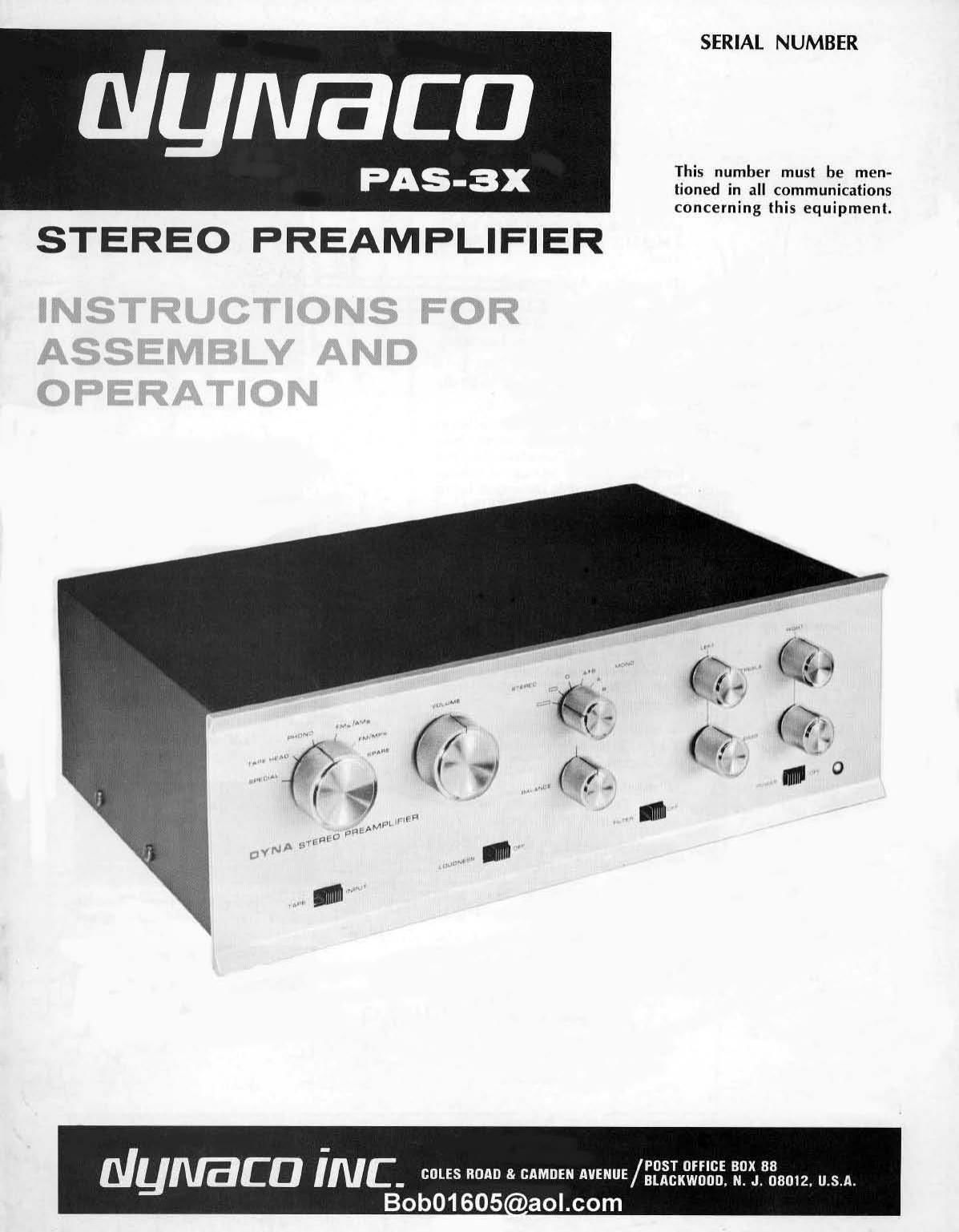
Dynaco PAS 3X Owners Manual

Extracted text from Dynaco PAS 3X Owners Manual (Ocr-read)


Page 1

SERIAL NUMBER

ulymaca

PAS-3x This number must be men-

tioned in all communications

concerning this equipmenl.
STEREO PREAMPLIFIER

Nymca iNE_ COLES noun a. cmnm Minus/"5I 0" 30X 88

BLACKWOUD. N. .I. 08012, USA.
Bob01605 o aol.com

Page 2

SPECIFICATIONS

Inputs:

Outputs:

Controls:

Tone Control Range:

Distortion:

Response:

Transient performance:

Hum and noise:

Gain:

Impedancos:

Tubes:

3 stereo low level: RIAA phono,
NAB tape head (7%"), Special
(optional second phono, micro-
phone, etc.). 4 stereo high level:
FM-AM, FM-Multiplex, Spare,
Tape.

Tape output. Audio output.

Selector, Volume, Balance, Blend.
Individual Treble and Bass for each
channel, Tape Monitor, Loudness.
Scratch Filter, Power.

: 14 db at 20,000 cycles. v- 20 db
at 20 cycles.

Less than 0.05% intermodulation at
2 volts (sufficient output to drive
any amplifier), Distortion does not
increase at lower settings of volume
control. Harmonic distortion below
the measurement capabilities of
regular commercial grade test
equipment.

1 .5 db 10 cps to 40 kc. Response
not affected by position of volume
control.

Passes square waves without ringing
and with minimum deformation
from 20 cps to 20,000 cps. No over-
shoot or bounce on pulse type sig-
nals. Instantaneous recovery from
overload.

2 microvolt equivalent noise on
RIAA. 74 db below level of 10 milli-
volt signal.

60 db at 1,000 cycles on RIAA; 60
db on Tape Head; 20 db on Radio
and other high level inputs.

Output impedance 1,000 ohms; ter-
minating impedance 100,000 ohms
or higher. Low level input im~
pedance 50,000 ohms; high level
input impedance 250,000 ohms.

4 12AX7/ECC-83; l 12x4; 1 sele
nium stack.

Bob01 605@aol.com

no

.25

em

Asseogasz.

m
ramumcv. cvs

Equalization.

n van V296

vat

#
g
E
E
E
..
E
s
§
§

0

lul

20 IA
roommates

Harmonic distortion percentage.

2 u aismrimx
.05 Ms

as IV zvsvm}
nutmhvoua

IM distortion.

10 KC squan- wave from Dynakil
(below! is much like original
labour-J.

Page 12

19( ) Connect the red wire from SS wafer 13 lug #2 to PC-G
terminal #3 (S).

20( ) Connect the green wire from SS wafer B lug #6 to
PC-6 terminal #8 (S).
21( ) Connect the green wire from SS wafer B lug #8 to

PC-G terminal #9 (S).

22( ) Connect one green wire from SS wafer C lug #1 to
MS lug #1 (S).

Connect the green wire from SS wafer C lug #2 to
PC-6 terminal #7 IS).

Connect the short black wire from water C lug #3 to
PC-G eyelet #11 (S) (In addition to the wire already
soldered below the board).

Connect the green wire from SS water C lug #5 to
eyelet #13 of PC-G (S).

Connect the green wire from SS wafer (. lug #6 to
left socket (long lug) #3 (S).

Connect the green wire from SS wafer C lug #7 to
left socket #2 IS).

Connect the green wire from SS wafer ( lug #8 to
left socket #1 (S).

Position the long black wire from SS wafer C lug
#3 across the rear of the wafer. and below the cen-
ter rotor shaft. Wrap this wire around the three
green wires from lugs #6, #7 and #8. and connect
it to the ground (short) lug of left channel input
socket #1 (S).

Connect the green wire from SS wafer C lug #9 to
left socket #4 (5).

Connect the green wire from SS wafer C lug #10 to
left socket #5 (S).

Connect the green wire from SS wafer C lug #11 to
left socket #6 (S).

Connect the green wire from SS wafer C lug #1 to
left socket #8 (S).

Connect the green wire from MS lug #3 to left socket
#7 (S).

Connect the green wire from PC~5 eyelet #7 (top of
the board) to left socket #9 (5).

Connect the black wire from PC-5 eyelet #1 (top of
the board) to the center of the bare wire between
right ground lugs #8 and #9 and left ground lugs #8
and #9 (3).

Insert the line cord from the outside and pull about
seven inches through the grommet. Tie a knot in the
00rd so that about five inches remains inside the knot.
Position the cord under the outlets as shown and con-
nect one end to lug A of outlet #2 (S). Connect the
other end to lug B of outlet #2 (S).

23(

24(

25(

264

271

28(

29(

30(

31I

32(

331

34I

35(

361

37(

Special" Input

The Special input 03ers a variety of options which can
provide considerable flexibility for the user. If left unwired.
the equalization characteristic (augmented by the tone
controls) is suitable for 78 rpm records. When wired as
indicated below, it can be used for a low level stereo
source or one channel can be wired for one monophonic
input, and the other channel for a different mono input.
Then the A and "B selector function of the stereo-
mono (blend) switch enables selection of either source.
and the blending function permits limited mixing of the
two signals at the audio output.

Please note that each channel can be wired for only one
function at a time. If you change from one characteristic
to another. be sure that you first remove all special wiring.
Factory assembled preamplifiers are connected for micro-
phone inpu! on both channels.

a. Microphone [Dynamic or Velocity types)

A microphone requiring standard 50K ohms load imped»
ance may be wired as shown in the pictorial diagram
(crystal or ceramic mikes cannot be used with the PAS
preamp). The right channel is wired by connecting a 3"
red wire from switch wafer B, lug #9 (S). to PCv6 eyelet
*5 (S). The left channel is connected with a 3% green
wire from switch wafer B. lug #3 (S) to P06 eyelet
#12 (S).

b. Magnetic Phone Cartridge

A second magnetic phono cartridge can be connected on
the right channel by wiring a short link of wire from lug
#9 to lug #ll of switch wafer B (solder both). For the
left channel. connect a wire between lug #3 and lug #5 of
wafer B (solder both),

c. Crystal or Ceramic Phone Cartridge

A ceramic or crystal cartridge ( 1/1 volt output or greater)
may be connected by first wiring the input for Microphone
as in paragraph a" above. Then remove the wire to input
socket #3 on the back panel of the preamp and solder a
3.3 meguhm one-half watt resistor between (in series with)
the wire and the long lug of the input socket. The resistor
leads should be cut to /2 to avoid excess bare wire. Do
this for each channel if a stereo cartridge is to be used.

:1. Tape Head

A second 71/2" NAB tape head input may be connected
by wiring a short Link of wire from lug #9 to lug #10 of
switch wafer B for the right channel (solder both), and
from lug #3 to lug #4 of water B (solder both) for the
left channel. As there is no standard equalization for 33/.
speed, the. tone controls may be needed for optimum results
with such tapes.

Completion

Carefully inspect all the wiring to make sure that it
agrees with the pictorial diagrams and the photographs.
Because the pictorials must be exaggerated for clarity, the
photographs best define lead placement. Note particularly
the placement of the wires leading the selector switch. The
green wires to the rear (C) water of the switch should be
kept above the chassis and grouped together, and the. red
wires to the front (A) wafer should be grouped together
and kept close to the chassis. Be sure that no twisted pairs
of wires are positioned across the circuit boards.

Insert the four 12AX7 tubes into the sockets on the cir-
cuit boards. The 12x4 tube goes into the 7 pin socket on
the chassis. Install the pilot light. Each rubber foot is in-
stalled in a corner hole in the bottom plate by inserting a
#6 screw through the foot so that the head is rewssed, and
securing it with a nut on the inside of the bottom plate.
The other two holes in the bottom plate are used only with
the brackets for cabinet installations. Install the cover and
bottom plate. and secure them with the {our sheet metal
screws through the sides. Remove the paper backing from
the adhesive identification label, and smooth it into posi-
tion on the bare part of the back panel.

12 Bob01605@aol.com