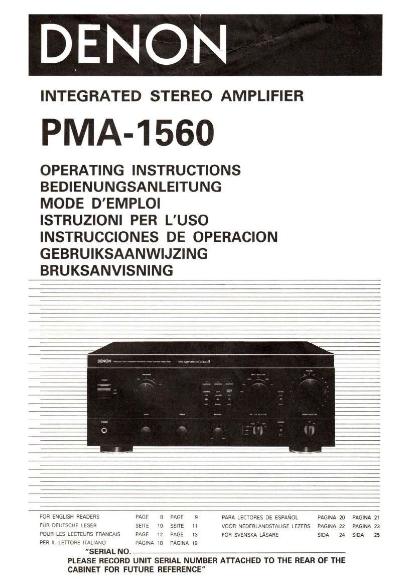
Denon PMA 1560 Owners Manual
This is the 26 pages manual for Denon PMA 1560 Owners Manual.
Read or download the pdf for free. If you want to contribute, please upload pdfs to audioservicemanuals.wetransfer.com.
Extracted text from Denon PMA 1560 Owners Manual (Ocr-read)
Page 1
INTEGRATED STEREO AMPLIFIER
PMA-1560
OPERATING INSTRUCTIONS
BEDIENUNGSANLEITUNG
MODE D'EMPLOI
ISTRUZIONI PER LUSO
INSTRUCCIONES DE OPERACION
GEBRUIKSAANWIJZING
BRUKSANVISNING
FOR ENGLISH READERS PAGE 8 PAGE 9 PARA LECTORES DE ESPANOL
PAGINA 20 PAGINA 21
FUR DEUTSCHE LESER sang 10 same 11 VOOR NEDERLANDSTALIGE LEZERS PAGINA 22 PAGINA 23
POUR LES LECTEURS FRANCAIS PAGE 12 PAGE 13 FOR SVENSKA LASARE SIDA 24 SIDA 25
PER u. LEWOPF ITALIANO PAGINA we PAGINA 19
"SERIAL NO.
PLEASE RECORD UNIT SERIAL NUMBER ATTACHED TO THE REAR OF THE
CABINET FOR FUTURE REFERENCE"
Page 2
0 FOR UNITED KINGDOM MODEL ONLY
CONNECTING THE MAINS PLUG:
This unit operates (mm a 240V ac 50 Hz mains supply.
IMPORTANT
The wires in the mains lead are coloured in accordance with the
following code:
Blue: Neutral
Brown: Live
As the colours of the wires in the mains lead of this apparatus may not
correspond with the coloured markings identifying the terminals in
your plug. proceed as Iollows:
The wire which is coloured BLUE must be connected to the terminal
which is marked with the letter N or coloured black
The wire which is coloured BROWN must be connected to the
terminal which is marked with the letter L or coloured red.
DO NOT MAKE ANY CONNECTION TO THE LARGER PIN MARKED
WITH THE LETTER E OR BY THE SYMBOL 7 OR COLOURED GREEN
0R GREEN-AND-YELLOW.
Disconnect the mains plug irom the supply socket when not in use.
EG-Konformititserklirung
CE
DENON Electronic GmbH
Halskestr. 32
4030 Ratingen 1
Die
erklén als Hersteller/lmponeur, dais das in dieser
Bedienungsanleitung beschriebene Gerat der
Vorschrift 868/1989 nach Amtsblattverft'igung
Technischen
im Amtsblatt
des Bundesministers ftir Post und Telekommunikation
entspricht.
Des lnverkehrbringen der vorliegenden Typenreihe ist der
Priifstelle der Bundesrepublik Deutschland (ZZF) fristge-
recht angezeigt worden.
DENON Electronic GmbH
Halskestr. 32, 4030 Ratingen 1
PRECAUTIONS FOR INSTALLATION
Leave at least mom of space between this unit and
any other component placed above.
SICHERHEITSMASSNAHMEN BEIM EINBAU
Lassen einan Mindestabstand von 10 cm zwischen
diesern Gerét und der enderen Komponente, die
darautgestellt wird.
PRECAUTIONS D'INSTALLATION
Prévoir un espace d'au moins 10cm entre l'unité et
tout autre appareil se trouvant au-dessus.
VOORZORGSMAAI'REGELEN
Bij pleatsing dient u een ruirnte van minstens 10 cm
open to laten tussen dit toestel en een ander erop
geplaatst komponent
FORSIKHGHETSATGARDER VID INSTALLATIONEN
Se till at! det finns minst 10 cm mellanrum mellan
appereten och en ev, annan apparet som stalls
ovanpa.
I
HIII I",
I
PRECAUZIONI PER L'INSTALLAZIONE I 10
Lesciate uno spazio libero di almeno 10 cm fra Q -) 1 102' °; march
quest'unite e qualsiasi altro componente che e \ v we 0 'lm' '
collocato sopra la stessa. U W ; -' " °" R
0 :9 10cm 0 pm
PRECAUCIONES PARA LA INSTALACION \ ? $ % n A 12cm D'p'
Dale por lo menos 10 cm. de especio entre esta (7 a 10:: :IlaTx;
unidad y cualquier otro componente situado sobre }
elle.
Page 8
OPERATION
PREPARAHON
1. CHECKING CONNECTIONS
0 Make sure that all the connections are proper by referring
to the back panel.
0 Check the polarity (positive and negative) of connections.
and the directivity of stereo separation (right cord to right
channel terminal, and left cord to left channel terminal).
0 Check the directivity of pin cord connection.
2. SETTING OF EACH KNOB
0 Turn the volume control knob counterclockwise, to "".0
0 Set the rotary knob to "flat".
0 Set SOURCE DIRECT, LOUDNESS, SUBSONIC, and MUT-
ING to "OFF (1.)".
After checking the above items, turn on the power, the amplifier is
set in the ready mode in a few seconds after the power LED is lit.
PLAYING A RECORD
1. Set the INPUT SELECTOR switch to PHONO".
2. Operate the turntable and play the record.
3. Turn the volume and tone controls to yield an appropriate
volume and sound quality.
PLAVBACK 0F CD PLAVER
I. Set the INPUT SELECTOR switch to "CD".
2. Operate the CD player.
3. Turn the volume and tone controls to yield an appropriate
volume and sound quality.
RECEPTION 0F RADIO PROGRAMS
1. Set the INPUT SELECTOR switch to "TUNER".
2. Operate the tuner to receive a radio program.
3. Turn the volume and tone controls to yield an appropriate
volume and sound quality.
CONNECTIONS 0F AUDIO EQUIPMENT T0 AUX TERMINALS
'I. Set the INPUT SELECTOR switch to "AUX" Position.
2. Operate the Audio equipment Systems.
3. Turn the volume and tone controls to yield an appropriate
volume and sound quality.
PLAVBACK WITH TAPE DECK
1. Set the INPUT SELECTOR switch to "TAPE-1" or "TAPE-2".
2. Operate the Tape Deck.
3. Turn the volume and tone controls to yield an appropriate
volume and sound quality.
RECORDING WITH TAPE DECK
I. Set the REC OUT SELECTOR to the program source you wish
to record.
2. Start the playback of the program source.
3. Start recording with the component connected to "TAPE-1" or
TAPE-2".
o In the PMA-1560. the REC OUT signal and the speaker
Iheadphone) signal are output via separate circuits so that
knobs and switches related to the tone and volume have no
effect whatsoever on the sound that is recorded. Also, since
the recording funtion is selected by the REC OUT SELECTOR,
the free program source can be played through the speakers
(or headphones) even during recording.
0 MONITORING THE RECORDING
A recording in progress can be monitored if a tape deck with
three individual heads for recording and playback is used. A
tape deck in which a common head is used for both recording
and playback cannot be used to monitor recordings When a
recording is being made using TAPE-1, selecting TAPE-1 with
the lNPUT SELECTOR will engage the RECORDING MONITOR
and pemit a check of the recording condition.
CAUTION
Protective Circuit
This set is equipped with a high speed protctive circuit. This
circuit protects the internal circuitry from damage due to
large currents flowing when the speaker jacks are not
completely connected or when an output is generated by a
short circuit. This protective Circuit's operation cuts off the
output to the speakers. In such a case, be sure to turn the
power to the set off and check the connections to the
speakers. Then turn the power on again. After muting for
several seconds, the set will operate normally.
e AC OUTLETS . . . For Mum-voltage model.
AC outlets are used for connecting amplifier component
units, such as tuner, turntable, tape deck, etc.
o SWITCHED (Total capacity: 120 W):
This outlet is turned ON/OFF when main power
switch is turned on/off.
o UNSWITCHED (Capacity: 240 W)
These outlets are always ON whether power switch
is on or OFF.
0 LINE VOLTAGE (Voltage select switch) . . . For Multi-
Voltage model only.
" The desired voltage may be set with the
VOLTAGE SELECTOR KNOB on the
back panel using a screw driver. fig
' Do not twist the VOLTAGE SELECTOR
KNOB with excessive force. It may be Q
damaged.
' II the voltage select switch does not turn
smoothly. see qualified servicemen.
Page 12
SUBSONIC (Commuteteur do filtre subsonique)
Ce commutateur est utilisé pour eviter Ia vibration d' en-
ceinte subsonique due a la vibration du moteur du lecteur
ou d'un disque voilé, etc., lors de la lecture avec un lecteur
connecté.
PHONO SELECTOR (Commutateur de selection de
cellule)
Ce commutateur est réglé salon le type do cellule du iecteur
a utiliser.
a MC: Utilise lorsqu'une cellule MC (a bobine mobile)
avec une sortie de moins de 0.5 mV est utilisée.
0 MM: Utilisé lorsquune cellule MM (a aimant mobile)
avec une sortie de 2 rnV ou plus est utilisée.
FONCTIONNEMENT
PREPARATION
1. VERIFICATION DES CONNEXIONS
o Sassurer que toutes les connexions sont correctes en se
reponant au panneau arriere.
o Véritier la polarité (positive at negative) des connexions et
la directivité de la separation stereo (cordon de droite a la
borne de canal droit et cordon gauche a la borne de canal
gauche).
- Vérifier la directivité du cordon de connexion a broche.
Z. REGLAGE DE CHAOUE BOUTON
O Tourner le bouton de commando cle volume dans le sans
contraire des aiguilles dune montre vers la position "0'.
o Placer le bouton rotatif sur "flat" (plat).
o Placer les commutateurs de source directe (SOURCE
DIRECT), compensation physiologique (LOUDNESS), sub-
sonique (SUBSONIC) at do mise en sourdine (MUTING) sur
la position hors circuit "OFF ( j. )".
Apres la verification des points cites ci-dessus, mettre l'appareil
sous tension, I'amplificateur étant régle darts Ie mode "prét" en
quelques secondes apres I'allumage du vovant (LED) de mise
sous tension,
LECTURE D'UN DISOUE
1, Placer le sélecteur d'entrée (INPUT SELECTOR) sur la position
PHONO.
2. Faire fonctionner la platine tourne-disque et lire un disque.
3. Tourner les commandes de volume at de tonalité pour obtenir
un volume et qualité sonore appropriés.
LECTURE D'UN LECTEUR DE DISOUE COMPACT
1. Placer le sélecteur d'entrée (INPUT SELECTOR) sur CD",
2. Faire (onctionner le lecteur do disque compact.
3. Tourner les commandes de volume at da tonalite pour obtenir
un volume et qualité sonore appropries.
RECEPTION DE PROGRAMMES DE RADIO
1. Placer Ie sélecteur dentrée (INPUT SELECTOR) sur TUNER".
2. Faire fonctionner Ie syntoniseur pour recevoir un programme
de radio.
3. Tourner les commandes de volume at de tonalité pour obtenir
un volume et qualite sonore appropriés.
CONNEXIONS D'UN EOUIPEMENT AUDIO AUX BORNES AUXI-
LIAIRES (AUX)
1. Placer le sélecteur d'entrée (INPUT SELECTOR) sur la position
AUX".
2. Faire fonctionner les systemes d'equipement audio.
3. Tourner les commandes de volume at de tonalite pour obtenir
un volume et qualite sonore appropries.
LECTEUR AVEC UNE PLA11NE CASSETTE
1. Placer Ie sélecteur d' entree (INPUT SELECTOR) sur la position
TAPE- 1" (platine- 1) cu "TAPE 2" (platine 2).
2. Faire fonctionner la platine cassette.
3. Tourner les commandes de volume et de tonalite pour obtenir
un volume et qualité sonore appropries.
ENREGISTREMENT AVEC UNE PLATINE CASSETTE
1.
2.
3. Commencer I'enregistrement avec l'appareil connecté a la
Placer le selecteur de sortie d'enregistrement (REC OUT
SELECTOR) sur la source de programme a enrogistrer.
Commencer Ia lecture de la source de programme.
prise TAPEJ (platine-1) ou "TAPE-2" (platine»2).
Dans le PMAJSSO le signal de sortie denregistrement (REC
OUT) et Ie signal d'enceinte (écouteur) sont envoyés via des
circuits separes de sorte que les boutons et commutateurs lies
a la tonalite et de volume naient pas d'effet quelconque sur le
son enregistre.
Puisque la fonction d'enregistrement est sélectionnée par le
sélecteur de sortie denregistrement (REC OUT SELECTOR). l8
source de programme Iibre peut étre Iue via les enceintes (ou
écouteur) méme pendant l'enragistrement.
CONTROLE DE L'ENREGISTREMENT
Un enregistrement en cours peut étre contrélé si une platine
cassette avec trois tétes individueIles pour I'enregistrement et
la lecture est utilisée. Une platine cassette dans laquelle une
Iéte ordinaire est utilisée pour lenregistrement et la lecture a
la fois ne peut pas étre utilisée pour controler I'enregistre-
ment. Lorsqu'un enregistrement est Iait en utilisant Ia platine-
1 (TAPE-1), en selectionnant TAPEJ (platine-1) avec le sélec-
teur d'entree (INPUT SELECTOR), le moniteur d'enregistre-
ment (RECORDING MONITOR) est enclenche et permet una
verification de l'enregistrement.
ATTENTION
Circuit do protection
Cet appareil est equipe dun circuit de protection de grands
vitesse. Ce circuit protege le circuit interne contre les
dommages provoqués par des courants Ions qui passent
lorsque les prises denceinte I-Ie sont pas completement
connectées ou quand une sortie est générée par un
court-circuit. Ce circuit de protection coupe la sortie vers
les anceintes. Dans un tel cas, sassurer de mettre l'appareil
hors circuit at de verifier les connexions aux enceintes.
Puis remettre l'appareil sous tension. Apres une silence de
quelques secondes, Iappareil fonctionne normalement.
I Sonics CA . . . Pour les modeles mum-tension.
Les AC OUTLETS (sorties CA) peuvent étre utilisées
pour enficher des cordons d'alimention dappareils
connectés a I'ampli, tels que tuner, lecteur de disque ou
magnétophone.
o SWITCHED (en circuit) (Capacité max: 120 W)
Ces alimentations sont commandées par linterrup-
teur d'alimentation principal (POWER), et ouvertes
(ON) et coupées (OFF) par cet interrupteur.
- UNSWITCHED (hors circuit) (Capacité max.: 240 W)
Ces alimentations n'est pas connectée e l'interrup-
teur (POWER).
13