Decca 66 service manual
This is the 6 pages manual for decca 66 service manual.
Read or download the pdf for free. If you want to contribute, please upload pdfs to audioservicemanuals.wetransfer.com.
Extracted text from decca 66 service manual (Ocr-read)
Page 1
[an rights reserved. This service data sheet In the copy-
right or Wmmss e mac-mic. Tainan and may not
be reproduced, In whole or in part, without permission]
TRADER" SERVICE SHEET
12,25
MPLOYING an elliptical moving coil
speaker for reproduction of the
middle and lower register, and an
electrostatic speaker for high note repro-
duction, the Decca 66 is a. 5-valve (plus
rectifier and tuning indicator) A.M./F.M.
table receiver, designed to operate from
A.C. mains of 100»125V and 200-250V,
50c/s,
Model RGIOO is a 5-speed console auto-
radiogrem version of the 66, employing
the same chassis.
Release date and original prices:
Model 66 September 1955, £30 185 1d;
Model Réloo, August 1955, £41 145 8d.
Purchase mac extra.
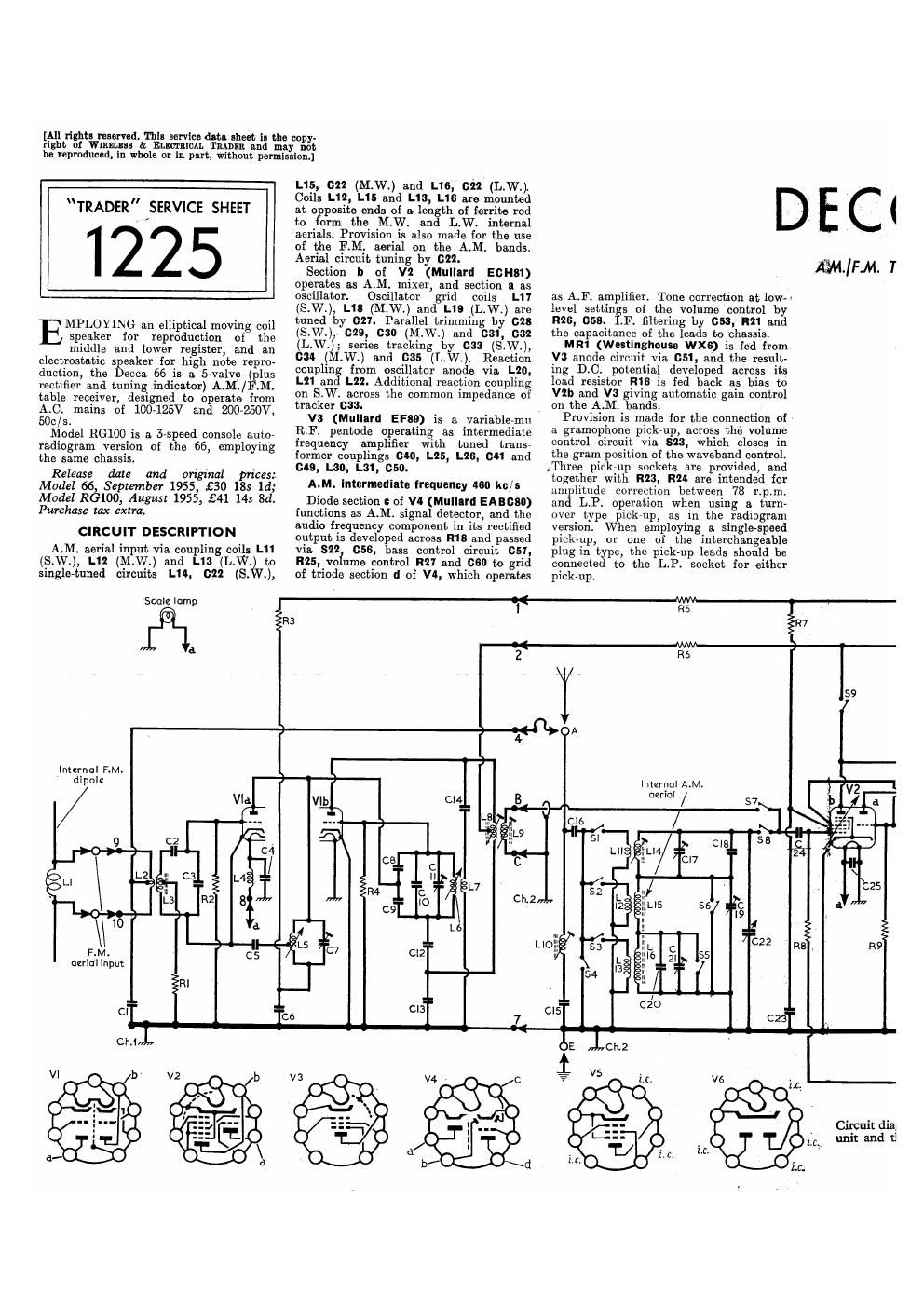
CIRCUIT DESCRIPTION
AM. aerial input via. coupling coils L1
(S.W.), L12 (M.W.) and L13 (L.W.) to
single-tuned circuits L111, 022 (S.W.),
Scolclomp
3
L15, on (MW) and 1.16, 022 (L.W.l
Coils L12l L15 and L13, L16 are mounted
at o posits ends of a length of ferrite rod
to 0m the M.W. and L.W. internal
aerials. Provision is also made for the use
of the RM. aerial on the A.M. bands.
Aerial circuit tuning by 622.
Section II of V2 (Mullard EOH81)
operates as A.M. mixer, and section a as
oscillator. Oscillator grid coils L11
(S.W.), L18 (M.W.) and L19 (L.W.) are
tuned by 027. Parallel trimming by 028
(S.W.), 019, cm) (M.W.) and 031, 032
(L.W.); series tracking b 633 (S.W.),
034 (M.W.) and 035 (L. .). Reaction
couplin from oscillator anode via L20,
L21 an L22. Additional reaction coupling
on SW. across the common impedance of
tracker 093.
V3 (Mullard EF89) is a variable-mu
RF. pentode operating as intermediate
frequency amplifier with tuned transr
former couplings cm, L25, L26, 0111 and
cm, L30, L31, cso.
AM. Intermediate frequency 1160 kc/s
Diode section a of V4 (Mulluld EABGSO)
functions as A.M. signal detector, and the
audio frequency component in its rectified
output is developed across R18 and passed
via, 822 (:58, bass control circuit 051,
R25. vo ume control R21 and 060 to grid
of triodo section d of VD, which operates
DEC<
as A.F. amplifier. Tone correction at low-l
level settin s of the volume control by
R26, 058. .F. filtering by 053, R21 and
the capacitance of the leads to chassis.
MR1 (Westinghouse WXG) is ted from
V3 anode circuit via 051, and the result-
ing DC. potential developed across its
load resistor R18 is fed back as bias to
V2|1 and V3 giving automatic gain control
on the A.M. bands,
Provision is made for the connection of ,
a gramophone pick-up, across the volume
control circuit via, 823, which closes in
the gram position of the waveband control
,Three pick-up sockets are provided, and
together with R23, R24 are intended for
amplitude correction between 78 r.p.m.
and LP. operation when using a, turn»
over type pickrup= as in the radiogram
version. When employing a single-speed
pickup, or one of the interchangeable
plug-in type, the pick~up leads should be
connected to the LP. socket for either
pick-up.
AIM/FM. 1
Inurnal F.M.
dipole
. 1: éé L '
R3 R7
2t F25
Intzrna! A.M.
aerlol /
Page 2
Resistance-capacitance coupling by R29,
66 and R31 between V!!! and pentode
output valve V5 (Mullard ELSA).
Treble-tone control by R36 which
shunts (:65 across V5 control grid circuit
and also controls the output of the electro-
static speaker. A polarizing voltage is fed
to this speaker Via. Ru. Negative feed-
back tone correction between V5 anode
and control grid circuit via 081, and by
the frequency correction network R10,
can, an, rm, cm, an, ass, use, new
and 068 between T1 secondary winding
and VIM grid circuit. 324 closes on M.Wi
and L.Wi to increase the treble response
on these bands.
H,T. current is supplied h I.H.C. full-
wave rectifying valve V8 ( ullard E280)
HiT. Smoothing by R30, H36, L32 and
Electrolytic capacitors 062, 083, G12 and
13.
Operation on FM.
Balanced 809 RM. aerial input via coup~
ling coil L2 to fixedtunecl aerial circuit L3,
Supphment to Wireless Cr»
Electrical Trader, 19 November 1955
02, 03. Section a of V1 (Mullarfl E6685)
is an earthed-cathode RF. amplifier
V1a anode/ grid inter-electrode capaci-
tance is neutralized by cs. The amplified
output from V1: is coupled via single-
tuned circuit L5, 01 to V), which
operates as an oscillator / mixer valve with
tuned oscillator grid circuit L6, 08, 09,
810, C11. EM. tuning is by means of the
cores of L5 and L6 which are ganged to
the common A.M./F.Ml tuning control.
Oscillator radiation is kept to a mini-
mum by means of OS, 09, 011, 013 which
form part of a. balanced bridge circuit to
prevent Oscillator voltages from passing
back into the RF. amplifier.
V2b and V3 form the tworvalve FlM.
intermediate frequency amplifier, which is
coupled by tuned transformers L8, L9;
038, L23, L21, 089; and discriminator
transformer L21, L28, L29, 041, to diode
sections a and h of V4, which are con
nected in a ratio detector discriminator
CCA 66 & R6100
F.M. Table Model and 3-speed Autoradiogram for A.C. Mains Operation
F.M. Intermediate frequency 10.1Mc/o.
The AtF. output of the ratio detector is
developed across 008, and is assed via
821 to the volume contro circuit.
Limiting is erformed by the flywheel
effect of D. i reservoir (:55. The limiting
voltage developed across 055 is fed back
as an AtGD. voltage to V3 suppressor
grid, but on S.VV. 810 closes to connect
the suppressor grid to chassis.
GENERAL NOTES
SWItches.-s1 614 are the wavehand and
radio/gram change-over switches ganged
in four rotary units beneath the chassis.
These units are indicated in the underside
illustration of the chassis and shown in
detail in the diagrams overleaf (0015, 5
and 6). The units are viewed here i
the direction indicated by the arrows in
location references E2 and E3. The
associated switch table, in column 3 over»
leaf, indicates the switch operations in
SIO\
circuit.
mé é,
Sl4
RIO
37
R27
Valumz
mi: diagram of the Decca 66. The lettered and numbered connections between the tuner
K and the main diagram correspond With those actually marked on the chassis of the unit.
R45
C7