Decca 46 service manual
This is the 4 pages manual for decca 46 service manual.
Read or download the pdf for free. If you want to contribute, please upload pdfs to audioservicemanuals.wetransfer.com.
Extracted text from decca 46 service manual (Ocr-read)
Page 1
H 111W111111111111111111111 llllufill
lllvlllllilllllllllll"lllllllllllllllllIlllllllllllllllllllllllll1llllllllllllllllll11lllllllllllllllllllllllllllllllllllil llll 11
TRADER" SERVICE SHEET
788
.1 llllllltl llll ll1l ll11l1l1lull1l 11
ESIGNEID to operate from A.(, 111
ll.(. mains or from self contained
batteries the Double Demo 46 is :1
4 who (plus metal rectifier) 511111111 porl
able supelliel. A loaded frann acxial pm
\ides the signal input 011 M.\\.11n1[ L. \\.
11nd 1n (\l€l'nlll aerial is mod on S. \\.
The mains \oltuue mugs i.» 100- 250 V.
The SAY. range is 16-50 m.
The introdudion of 11 metal rcctifiei
and the pennuuwut series connection of
who Hummus limo greatly simplified
Supplement to The Whaler: 6?
{Electrical Trader, October 19, 194g
DOUBLE
POST-WAR
the design as compared with pie \iar sets
0! the same type, reducing heat dissipa
tion mains/battoly change mar switch
ing, and widerrmlge Voltage adjustment
complexity. As the plugin frame aerial
and the speaker are attached to the
chassis7 this can be removed from the
cabinet as a working unit.
Release Llllll and original price:
1946; £15, I'omplctc with baffcrim,
:95 4.9. 6r]. purchase Last.
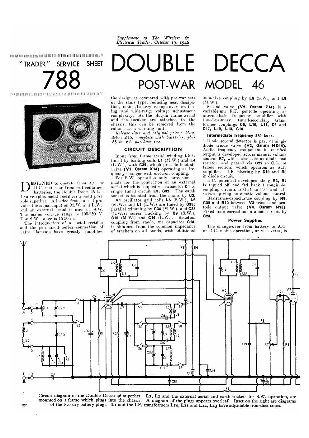
CIRCUIT DESCRIPTION
input from frame aerial winding L2 is
tuned by loading coils L1 (M,VV.) and LA
(l..W,), with 632, which precede heptode
\alve (V1, Osram X14) operating as fre»
quency changer with electron coupling.
» For S.\V. operation only, provision is
made for the connection of an external
aerial which is coupled via. capacitor 01 to
single tuned circuit L3, 032. The earth
socket is isolated from the mains by 03.
V1 oscillator grid coils L5 (SW), L8
(\l W) and L1 (L W.) are tuned by 033;
paiallel trimming by 034 (M. W. ), and C35
(L..W); seiies tracking bv 08 (S.W.),
610 (M W.) and GI! (L.W.). Reaction
coupling from anode, via capacitor 614,
is obtained from the common impedance
of trackers on all hands, with additional
May.
ploy
DECCA
MODEL 46
inductive coupling by LS (SM/.1 aml L9
(XLWJ.
Second valve (V2, osram 114) is 11
vui'iablevmu [LR pentode operating as
intermediate l'requencv amplifier with
tuncv'dpiimaiy, tuned secondary trans,
formei couplings GS, L10, L11, 06 and
011, L12, L13, 018.
Intermediate lraquenuy 380 kc/s.
lliode second detector is part of siugh-
diode triode valve (V2, Olram HDII).
Audio frequency component in rectified
output is developed across manual volume
control R1, which also acts as diode load
resistor, and passed via G21 to CI}. nl
triode section, which operates as Al.
amplifier. LF. filtering by 019 and R6
in diode circuit.
DJ). potential duvelupud along R8, R7
15 tapped off and fed back through 1h»
coupling circuits as GB. to F,(. and 1.)".
valves. giving automatic volume control.
Resistancercapacitance coupling; by H9.
022 and R10 between V3 triode 11nd penr
lode output valve (V4, OII'IM N15).
Fixed tone correction in anode circuit by
023.
Power Supplies
The change-over from battery to AC.
or D.C. mains operation, or vice versa, is
o
:5
VI
C4
1..
A
11 C32
#cao
12
1s : K
L4
5 K K 53
(2 ca:
E 3 C3
0 o
Circuit diagram of the Double Decca 46 superhet.
mounted on a frame which plugs into the chassis.
of the two dry battery plugs.
..,|
R3 R4
\-Il\.-
1 I 112
0 C6 3 cm
:- C|7 :1
111 L13 I
H-
\-4
V2 C21 V3
. =04 .
L5 57
C8 L8
116
L6 58
C34
c9 L9
CWT R7
Clé
c1;
:13 I 2C0
115 , f
L! and the I. F. transformers Lw, Lu and L12, L13 have adjustable iron-dust cores.
L], La and the external aerial and earth sockets for SHW operation, are
A diagram of the plugs appears overleaf. Inset on the right are diagrams