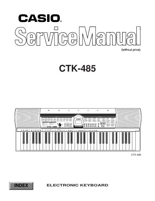
Casio ctk 485 service manual
This is the 20 pages manual for casio ctk 485 service manual.
Read or download the pdf for free. If you want to contribute, please upload pdfs to audioservicemanuals.wetransfer.com.
Extracted text from casio ctk 485 service manual (Ocr-read)
Page 1
Ñ 1 Ñ SPECIFICATIONS GENERAL Model: CTK-485 Keyboard: 61 standard-size keys, 5 octaves Tones: 100 Polyphony: 12 notes maximum (6 for certain tones) Auto accompaniment Rhythm Patterns: 100 Tempo: Variable (236 steps, = 20 to 255) Chords: 2 fingering methods (CASIO CHORD, FINGERED) Rhythm controller: START/STOP, SYNCHRO/FILL-IN Song Bank Tunes: 100 Controllers: PLAY/PAUSE, STOP, LEFT (ON/OFF), RIGHT (ON/OFF) Multi function display Name display: TONE, RHYTHM, SONG BANK name/number, keyboard settings name/ value Tempo: Tempo value, metronome, synchro standby, beat indicator Other functions Transpose: 12 steps (Ð6 semitones to +5 semitones) Tuning: Variable (A4 = approximately 440 Hz ± 50 cents) Volume: 0 to 9 (10 steps) Terminals Phones/output terminal: Stereo standard jack Output Impedance: 70 W Output Voltage: 2.4 V (RMS) MAX Power supply terminal: 9 V DC Power supply: Dual power supply system Batteries: 6 AA-size batteries Battery life: Approximately 2 hours (SUM-3/R6P)/4 hours (AM3/LR6) AC adaptor: AD-5 Auto power off: Turns power off approximately 6 minutes after last key operation. Enabled under battery power only, can be disabled manually. Speaker output: 2.0 W + 2.0 W Power consumption: 9 V . . . 7.0 W Dimensions (HWD): 91.0 ´ 32.2 ´ 9.0 cm (35 7/8 ´ 12 11/16 ´ 3 9/16 inches) Weight: Approximately 4.0 kg (8.8 lbs) (without batteries) CONTENTS Page Specifications ............................................................................................................................................ 1 Block Diagram ........................................................................................................................................... 3 Circuit Description ..................................................................................................................................... 4 Troubleshooting ........................................................................................................................................ 8 Adjustment ................................................................................................................................................ 9 Major Waveforms .................................................................................................................................... 10 Printed Circuit Boards ............................................................................................................................. 11 Schematic Diagrams ............................................................................................................................... 13 Exploded View ........................................................................................................................................ 16 Parts List ................................................................................................................................................. 17