Carvin asg 79 250a 25od 500 600
This is the 15 pages manual for carvin asg 79 250a 25od 500 600.
Read or download the pdf for free. If you want to contribute, please upload pdfs to audioservicemanuals.wetransfer.com.
Extracted text from carvin asg 79 250a 25od 500 600 (Ocr-read)
Page 1
ASG SERIES
POWER AMPLIFIERS
OPERATING/SERVICING MANUAL
The A86 series amplifiers are high-powered, dual-channel units deSigned to proVide high reliability under the stress of commercal
sound reintorcement conditions. The standard of quality (reflected in the speCitications) makes the ASG an excellent choice for
ClSCO studio or home applications as well.
Active electronic crossover networks have been included in the input Circuitry of each Channel. prowding the user With the chOice
at standard stereo operation or highpower monaurai bi-amping.
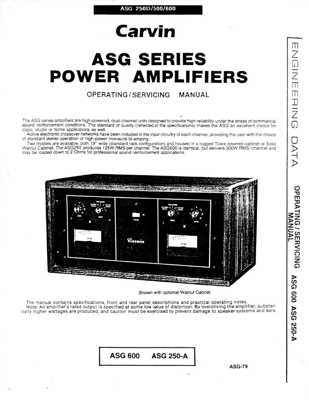
Two models are available. both 19" wide (standard rack configuration) and housed in a rugged Toiex covered cabinet or SONG
Walnut Cabinet. The ASGZSO produces 125W HMS per channel. The ASGBOO is identical, but delivers 300W HMS/channel ano
may :e loaded down to 2 Ohms tor protesstonal sound reinforcement applications.
Shown with optional Walnut Cabnet.
The manual contains spectlications, front and rear panel descriptions and practical operating notest
Note: An amplifiers rated output is specified at some low value of distortion. By overdriving the amplifier, substan-
tially higher wattages are produced, and caution must be exercised to prevent damage to speaker systems and ears.
ASG 600 ASG 250-A
ASG-79
VLVCI EiNieiziaNiEiNEiI
1VHNVIN
ONIOIAHBS / ONLLVHEIdO
V'OSZ 98V 009 OSV
Page 2
PANEL DESCRIPTION
5 . A
L I
LEIEL Mans POWER MDBDE LEeEL a 25:? 'IIIIYS 'APUEI 'PLIIIE :52:
SPEAKER "5 A
" OUTPUTS - FUSE F Effigy;
Illllllllilnilliilllilll Ill!llllllIlillii lllllllWlllllli lilliiillililliiltt
t a f ,. Osflio
(so [:1 e d ,ngfil EUQIMQEO
a \ a \ g g
a I a: s Q d 3 ~
I a a a c a 9 cl
Wflliljlil'iIIliiliIilil"lijlljfliIlHiIHIIHIHI, liiilll mg 1 \
. . I tilt. stilt \ '-
METER METER LINE SWIYEH LINE
UUIPUT OUTPUT
FRONT PANEL DESCRIPTION
LEVEL (A & B)
These controls regulate the Input level (hence the output volume) of their respective channels.
MODE (A a B)
A three-position switch offers the operator 3 choice of a FULL RANGE (fiat), HI PASS or L0 PASS response.
For normal stereo operation, both MODE switches must be set at FULL RANGE.
When Bi-Arnping. one channel should be switched to HI PASS, while the other channel is set at LG PASS. Complete
details are provided after the Panel Descriptions."
POWER
The Power Switch is located in the center of the front panel. Pushing the switch to the right turns the amplifier ON,
illuminating the L.E.D. Power indicator as well as the two level meters.
OUTPUT LEVEL METERS
Each channel is provided with an illuminated level meter. The meters are calibrated to read + 8 dB at full output, pro-
viding headroom for transients.
Normally, the meters should read below 0 dB to prevent excessive distortion.
REAR PANEL DESCRIPTIONS
SPEAKER OUTPUTS (A at B)
Two locking DSM connectors and one Va" phone jack are used for each channel. Pins 2 8t 13 of the DaM are wired to
gether as the "hot" lead, while pin 1 maintains ground. The heavy-duty 1/1 phone jack is wired in the standard manner.
All three jacks are wired in parallel.
SPEAKER FUSE (A E B)
A 15 amp fuse protects the speakers from severe malfunction conditions, such as high DC offset voltages, etc. Prov
tection may be increased under normal operation by reducing the fuse size to 10 amps. However, for continuous high-
power applications, the fuse must be left at 15 amps.
m (A Gt B)
Each channel offers both a DSF connector (for balanced lines) and 3 Ms" phone jack (for standard, singie~ended
sources). The grounds may be isolated from the chassis (see GROUND Switch).
LINE OUT (A A 5)
Located below the V" input jack, the LINE OUTjack can drive additional power amps, tape decks. etc. This is a post-
preamp jack. which means that the signal has been processed by the LEVEL control and/or the MODE swrtch. In other
words, when the Level control is fully counter-clockwise, no si nai is present at the LINE OUT Jack. Further, if the
Channels MODE switch is set at Hi PASS, the signal from the NE OUT Jack is filtered to a highpass response.
PRIMARY FUSE
A 10 amp fuse protects the amplifier and power supply from excessive current draw. Access to the fuse is gained by
pushing the fusehoider inwards, and turning counter-clockwise. Should the fuse fall, replace It with an identical fuse.
If the second fuse also fails, a problem Is indicated, and the amp should be serviced. To prevent unnecessary damage
to the amplifier, NEVER USE A FUSE WITH A HIGHER RATING.
LINE CORD
All Garvin equipment is supplied with 3conductor line cords, ending in grounding-type plugs. This arrangement will
greatly reduce the possibility of electrical shock. provided the equipment is used with 3-conductor grounding-type out-
lets, and provided those outlets have been properly wired. .
Under some circumstances. ground loops" can contribute unnecessary hum, and breaking" the loop by ustng a
2-conductor/3-conductor adaptor may reduce the hum. However, the A86 series amplifiers incorporate isolated input
jacks with a special GROUND switch (described below) which eliminates the need of such adaptors.