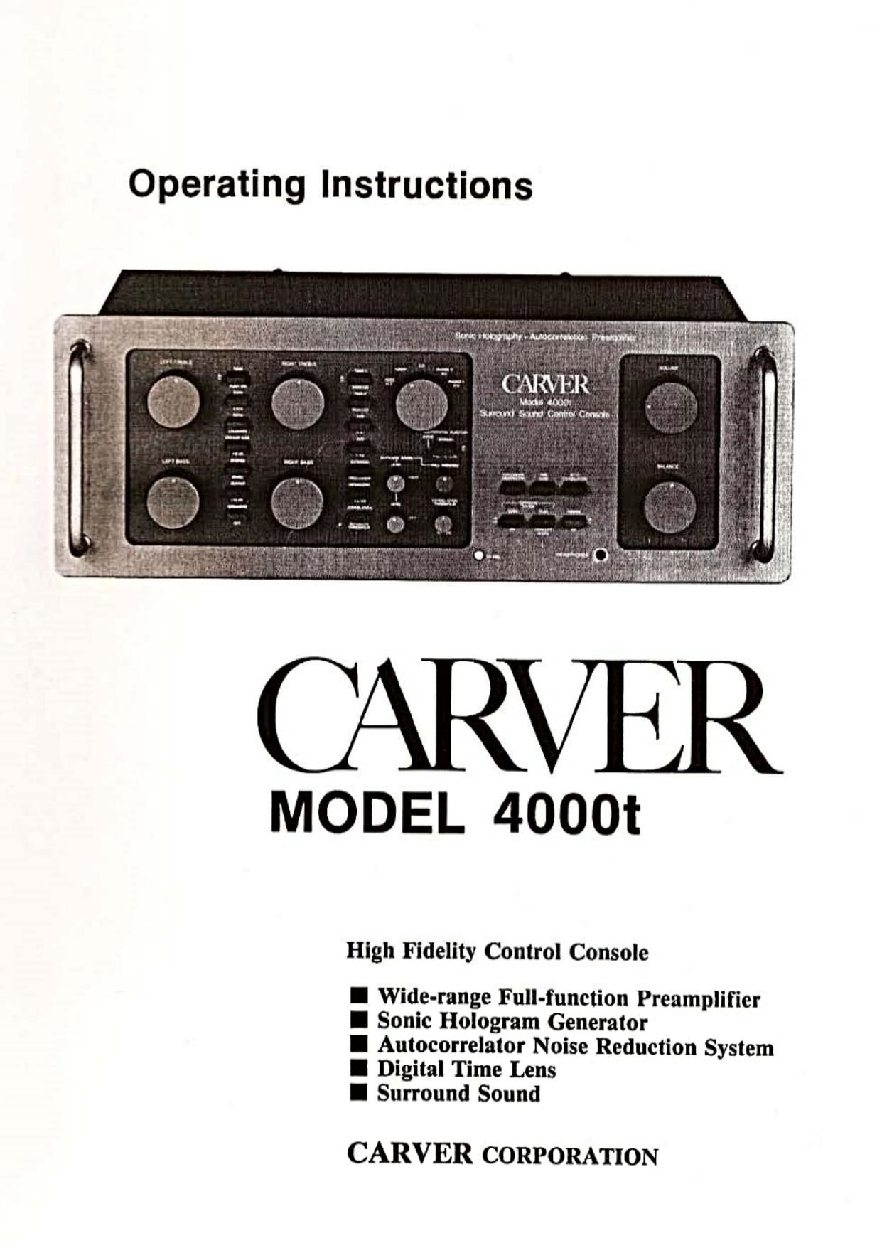
Carver 4000T Owners Manual
This is the 35 pages manual for Carver 4000T Owners Manual.
Read or download the pdf for free. If you want to contribute, please upload pdfs to audioservicemanuals.wetransfer.com.
Extracted text from Carver 4000T Owners Manual (Ocr-read)
Page 1
Operating Instructions
MODEL 4000i
High Fidelity Control Console
I Wide-range Full-function Preamplifier
I Sonic Hologram Generator
I Autocorrelator Noise Reduction System
I Digital Time Lens
I Surround Sound
CARVER CORPORATION
Page 2
CARVER MODEL 4000i
Table of Contents
i. Introduction ..............
ii. Notice to Purchaser
iii. Unpacking ...............
iv. Caution Notice
[.0 installation ........ . ................
2.0 Using Your 4000i:
A Quick Overview ..... . .................
3.0 System Wiring
Rear Panel Connections ................... . .............
3.1 Phone 1 and Phono 2 in
Selecting input Capacitance ..
3.2 Ground ....... . ....... ......
3.3 CD in ......
3.4 Tuner in ..
3
3
.u ..... nun
.5 Video/Aux .............
.6 Tape 1 and Tape 2 in
3.7 External Processor in
3.8 External Processor Out
3.9 Tape 1 and Tape 2 Out
3.10 Main Out ......... . .......................
3.11 Fuse
3.12 AC Sockets
3.l3 AC LineCord .............................
4.0 The Front Panel:
Preamplifier Controls ...............................
4.1 Power ..............
4.2 Headphones
4.3 Volume, Balance
4.4 Input Selector ............
4.5 lnfrasonic Filer
4.6Tape Monitor 1 and 2
4.7 Dubbing i and 2 .. .....
4.8 External Processor .
4.9 Stereo/Mono .......
4.10 Tone Controls ..
Tone 0n/Ofl'
8 kHz/2 kHz
N e-
NQQQQQOOQOOUUI
N
LI.
40 iii/Loudness .......... 11
4.11 Preamp Gain/ +10 dB .. 12
4.120utputl-15 dB .......... 13
4.13 Speakers Off .................... ................. 13
5.0 DIGITAL TIME LENS
5.1 What It Does .................................... 13
5.2 The Controls ......................................... 13
6.0 AUTO-CORRELATOR
Noise Reduction System ................... 14
6.1 What it Does ............. . 14
6.2 The Controls ................ 14
Auto-Correlator 0n/Off ....... 14
Correlation- Automatice Threshold. i4
Correlation Threshold- Manual ......... i4
LFCai ................................................ 14
7.0 SONIC HOLOGRAM
Stereo Image Processor 15
7.1 What it Does ......................................... 15
7.2 Making Holography Work:
Controlling Reflections .......................... 16
Speaker Placement .................... 16
Dealing with Reflected Sounds .............. 16
7.3 Making Holography Work:
Finding the Stereo Axis ......................... .. 18
7.4 Making Holography Work.
The Controls ...................................... 19
Sonic Hologram Generator 0n/0ii. .19
Holographic injection Ratio.
'Notrnal/Theoretical ........................ 19
7.5 Learning to Hear
the Holographic image ........................... 20
7.6 Effects of Speaker Design .. 21
7.7 Paient Notice ..................... . ........ . ......... 2|
8.0 SURROUND SOUND
Ambience Reproduction ............... ..... 21
8.1What It Does .................................... . 21
8.2 Choosing Loudspeakers
for Ambience ....................................... 22
8.3 Psychoactoustics
and Speaker Placement ..... . ....... 22
8.4 Using More Than
Two Ambience Speakers ........................ . 23
8.5 Connections ...... .. ........ 23
8.6 The Controls ............................. . ..... 23
9.0 Appendix A:
The Theory of Sonic Holography ..... 26
9.1 The illusion of Stereo Perspective
9.2 Stereo Recording and Playback 27
9.3 Sonic Holography:
Cancelling Acoustic Crosstalk .................. 27
10.0 Appendix B:
in Case of Difficulty... ................. 28
10.1 Hum ........ . ......................... . 28
10 2 Radio-Frequency interference ......... . 30
10. 3 Problem-Solving: Diagnostic Hints .. .. 31
Block Diagram ...................... . 29
10.4 Specifications 32
Page 11
the phono cartridge; some phono pickups have precisely equal
output levels in both channels, but many exhibit channel balance
errors of I to 2 dB. differing from sample to sample. because of
normal construction tolerances.
Tape recorders also commonly have input-to-output balance
shifts of l or 2 dB because of normal tolerances in the settings of
recording bias. internal calibration controls. and the tracking" of
the two sections of ganged Record Level and Output Level controls.
Balance errors may even differ from one brand or sample of tape to
the next.
Loudspeakers typically differ in sensitivity (efficiency") by
2 1 dB ormore from sample to sample due to normal con-
struction tolerances. and may vary further if you haven't matched
the settings of their midrange/tweeter controls. Moreover. if one
speaker is located near a wall and the other near an open doorway.
their output may be differently reinforced by room acoustics.
In each stage of the stereo system's electronics the two channels
can be expected to be well matched. But in an elaborate system with
many signal-handling stages (phono preamp. tone-control stage.
preamp output stage. equalizer. power amplifier. etc.) the tiny
balance errors in «each stage can add up to a significant total.
Finally. the two channels of the 4000t's own VOLUME control may
not track perfectly. especially at low-level settings. (When you find
yourself tuning the VOLUME control down below 9 o'clock. a
better approach is to set the OUTPUT switch to - [5 dB instead:
this optimizes the system SIN by minimizing residual circuit noise.
as well as allowing the VOLUME control to operate in the most
linear portion of its range.)
The controls in the left half of the front panel will be
discussed in the order in which an incoming signal en-
counters them. beginning with the input Selector. (The
controls below the Input Selector, which relate to the
4000ts special signal-processing functions. will be
discussed in a separate chapter.)
4.4 INPUT SELECTOR
This knob selects the program source which is to be
heard; if neither DUB switch is engaged, the same pro-
gram source is also connected to the tape recording cir-
cuits.
When you switch to a petition of the INPUT SELECTOR which
has no program source connected to it, you may hear some
"crosstalk" (leakage of signal from adjacent positions of the
switch). This can be eliminated, if desired. by installing "shorting
plugs" in the unused input jack: on the rear panel. (Do not imtaii
shorting plugs in unused output lacks. This would short-circuit the
output of the preamplifier.)
4.5 INFRASONIC FILTER
The selected input signal passes through an infrasonic
filter which has no effect on the audible tonal balance of
most recordings (even those with prominent deep bass)
but rolls off rapidly at frequencies below 20 Hz. When
the INFRASONIC FILTER switch is out. this filter is
bypassed: when the button is depressed the filter is
engaged. it is a good practice to leave the filter switched
on permanently.
The filter's group delay." an unavoidable consequence of its
rapid infrasonic attenuation. may produce a just-perceptible
alteration of low-frequency transient response. But in general any
audible effect of the filter will be beneficial, since reproduction of
infrasonic signals yields no benefit. These unwanted signals include
switching thumps. turn-on transients of associated components. the
thump produced in some FM tuners when tuned past a station. and
the transient produced when the phone stylus sets down in the
groove. If reproduced at high gain through a powerful amplifier.
such signals can damage loudspeakers.
Phonograph output signals are also contaminated with strong
infrasonic waveform components due to small and large disc warps.
motor rumble (especially in direct-drive units). acoustic feedback
and other externally-induced vibrations sensed by the phono stylus.
all of these amplified by the tone arm raonance (due to the stylus
compliance interacting with the effective arrn mass). These signal
components occur primarily in the frequency range from 2 Hz to is
Hz: if not stripped off the audio signal by an effective lnfrasonie
filter they will tend to waste amplifier power and cause excess
woofer cone motion. resulting in audible intermodulation distortion
(muddy bass).
Since the INFRASONIC FILTER is located in the
preamp circuit ahead of the tape outputs. it will also
prevent low-frequency overload of recordings by in-
frasonic contamination. However. it cannot remove any
low-frequency switching thumps produced by the tape
recorder itself; so if you have a recorder which produces
such thumps when going in or out of the playback
mode. reduce the setting of the VOLUME control until
the recorders output has stabilized.
4.6 TAPE 1 'AND TAPE 2 MONITORS
There ar'e no "tape" settings on the input Selector
switch. To listen to the playback output from a tape
recorder. 'simply depress the appropriate TAPE
MONITOR button. These monitor switches permit the
output from the tape machine to be heard regardless of
the setting of the input Selector. (If no tape machine is
connected to the input jacks. or if one is connected but
not operating, then depressing the corresponding TAPE
MONITOR button will produce silence.)
The TAPE MONITOR buttons govern only the selec-
tion of what signal is heard. They have no effect on the
signal which is fed to the preamp's Tape Out jacks for
recording; that selection is controlled exclusively by the
input Selector and the two Dub switches. If the Dub
switches are disengaged. then the program source
selected by the Input Selector is connected to the Tape
Out jacks for recording, regardless of the positions of
the TAPE MONITOR switches: i.e.. depressing TAPE
1 MONITOR to hear the playback from recorder #l
does not automatically perrnlt that playback signal to be
copied onto recorder #2. .
The principal purpose of the TAPE MONITOR but-
tons. of course. is to enable you to listen to tape
playbacks and to "monitor" the quality of new recor~
dings while they are being made.
In all cases. depressing TAPE l MONITOR lets you hear the
output from the recorder connected to the TAPE I jacks on the rear
panel. and depressing TAPE 2 MONITOR lets you hear the output
from recorder #2.
The identity of that output signal depends on the recorder's own
controls. in the playbaclt mode. of course. the signal is reproduced
from the tape. With a two-head recorder. when you put it into the
recording mode. normally the recorders input signal will also be
Page 35
CARVER CORPORATION
P.O. Box 1237
Lynnwood, Washington 98036
n: 4000!