Bryston 10 b owners manual

This is the 30 pages manual for bryston 10 b owners manual.
Read or download the pdf for free. If you want to contribute, please upload pdfs to audioservicemanuals.wetransfer.com.

Page: 1 / 30
bryston 10 b owners manual

Extracted text from bryston 10 b owners manual (Ocr-read)


Page 1

1OB-STD, 1OB-SUB and 1OB-LR Crossovers Frequency/Resistor Tables

The 1OB-SUB (for sub-woofer applications) and 1OB-STD ("standard" for general purpose
applications) are exactly the same except for the set of crossover frequencies available via the
front panel controls. The toB-LR, however, is a very different crossover. All three crossovers
are housed in a single rack height cabinet and all three are stereo units.

The 1OB-SUB, since it is intended for sub-woofer applications, has a low frequency set
of crossover points, between 40Hz and 500Hz.

The 1OB-STD, intended for general purpose bi-amp or tri-amp applications, has a much
broader set of crossover frequencies spaced between 70Hz and 4500Hz.

The 1OB-LR employs Linkwitz-Riley filters (24dB/octave) and has no front panel
controls for setting the crossover points. Instead, the crossover points are determined by eight
pairs of resistors. Each pair of resistors is located on a separate programming board (108-
LRPB) and each channel contains 4 programming boards. The circuitry for each channel is
located on its own crossover board, and each crossover board contains both a low pass and a
high pass Linkwitz-Riley filter. In some cases, the programming boards are dispensed with
and the pairs of programming resistors are soldered directly onto the crossover channel
boards. Since a Linkwitz-Riley filter is formed by cascading two 2d order filters, use only the
2'1d order tables in the 1OB-LR Frequency/Reisistor Tables beginning on page 22 for
determining the correct resistor values.

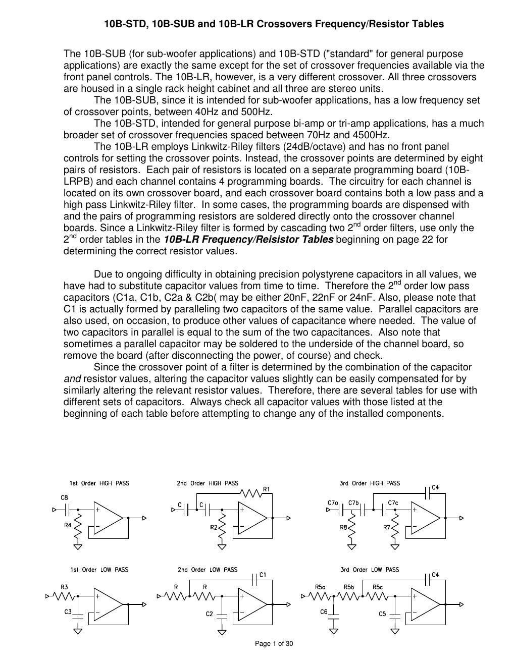
Due to ongoing difficulty in obtaining precision polystyrene capacitors in all values, we
have had to substitute capacitor values from time to time. Therefore the 2nd order low pass
capacitors (C1 a, C1b, C2a & 02b( may be either 20nF, 22nF or 24nF. Also, please note that
C1 is actually formed by paralleling two capacitors of the same value. Parallel capacitors are
also used, on occasion, to produce other values of capacitance where needed. The value of
two capacitors in parallel is equal to the sum of the two capacitances. Also note that
sometimes a parallel capacitor may be soldered to the underside of the channel board, so
remove the board (after disconnecting the power, of course) and check.

Since the crossover point of a filter is determined by the combination of the capacitor
and resistor values, altering the capacitor values slightly can be easily compensated for by
similarly altering the relevant resistor values. Therefore, there are several tables for use with
different sets of capacitors. Always check all capacitor values with those listed at the
beginning of each table before attempting to change any of the installed components.

13! Order HIGH PASS 2nd Order HIGH PASS R 3rd Order HIGH PASS C4
A A A 1
CB | |
c |_£| C70 C71) |__| C7c
-l> -I> -l>
R4 R2 R8 R7
Isl Order LOW PASS 2nd Order LOW PASS 01 3rd Order LOW PASS
R3 R R
-l> -I>
CS C2

3; l

Page 1 01 30