Bose amplus supplement s4
This is the 2 pages manual for bose amplus supplement s4.
Read or download the pdf for free. If you want to contribute, please upload pdfs to audioservicemanuals.wetransfer.com.
Extracted text from bose amplus supplement s4 (Ocr-read)
Page 1
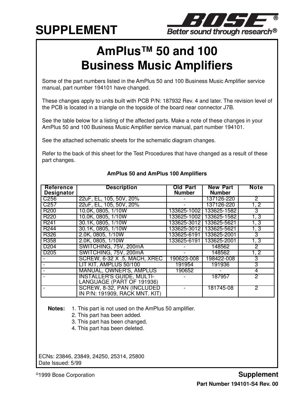
Note: Use the following tests for units built with PCB P/N: 187932 Rev. 4 and later. The revision level of the PCB is located in a triangle on the topside of the board near connector J7B. On the AmPlusª 10 amplifier, the change in value of resistors R241 and R244 as listed on the front of this sheet affects the gain level of the Channel 1 and 2 Line Outputs. As a result, the Gain Test on page 22 of the AmPlus 50 and 100 service manual, part number 194101 has changed as follows. Use the test setup parameters on page 21 of the service manual. 1. Gain Test; Source Input to Line Output 1.1 Apply a 100mVrms, 1kHz signal to the Channel 1 and 2 Source Inputs at J1. 1.2 Measure the output level at the Channel 1 and 2 Line Outputs at J5. 1.3 The output level at J5 should be -10.5 dBV ± 1.5 dB. Note: The information in parentheses applies to the AmPlus 100 amplifier only. On the AmPlus 50 (and 100) amplifiers, the change in value of resistor(s) R326 (and R358) as listed on the front of this sheet affects Channel 1 (and 2) output levels. As a result, the Bass Performance Test on page(s) (24 and) 30 and the High Pass Filter Test on page(s) (25 and) 30 of the AmPlus 50 and 100 service manual, part number 194101 have changed as follows. Use the test setup parameters on page(s) (21 and) 26 of the service manual. 9. (10.) Bass Performance Test 9.1 (10.1) Set up the unit under test as listed in the Test Setup Notes section. 9.2 (10.2) Apply a 31.5mVrms, 1kHz signal to the Signal Input jacks at J1. 9.3 (10.3) Reference a dB meter to the output level. This is the reference level. 9.4 (10.4) Perform the 20Hz and 100Hz tests as listed in Table (7 or) 13 below. Table (7 or) 13. Bass Performance Tests 10. (11.) Channel 1 High Pass Filter Test 10.1 (11.1) Set up the unit under test as listed in the Test Setup Notes section. 10.2 (11.2) On the main PCB, place the High Pass Filter switch (S4) to the HPF IN position. 10.3 (11.3) Apply a 31.5mVrms, 1kHz signal to the Channel 1 Source Input. 10.4 (11.4) Reference a dB meter to this output level. 10.5 (11.5) Apply a 31.5mVrms, 50Hz signal to the Channel 1 Source Input. 10.6 (11.6) Measure the output at Channel 1.It should be -7.0dBr ± 3dB (balanced inputs), or +28.0dBr ± 3dB (unbalanced inputs). Test Name Frequency Input (J1) Output (J6) Bass, 1kHz 1kHz31.5mV0dBr ± 0.1dB Bass, 20Hz 20Hz31.5mV-2.5dBr ± 2dB Bass, 100Hz 100Hz31.5mV+13.0dBr ± 2dB